
Circuit Diagram
Index 1428
DIGITAL_PRESSURE_GAUGE
Published:2009/6/17 22:21:00 Author:May
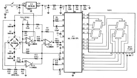
This electronic pressure gauge uses a Wheatstone bridge-type pressure sensor to drive a 31/2 digit A/D converter and a dis-play. IC1 is a pump (quad) that interfaces the bridge sensor to the A/D converter. RIG provides zero adjustment and R6 pro-vides full-scale calibration. Dl thru D4 provide temperature compensation. (View)
View full Circuit Diagram | Comments | Reading(4)
VOLTAGE_MONITOR
Published:2009/6/17 22:19:00 Author:May
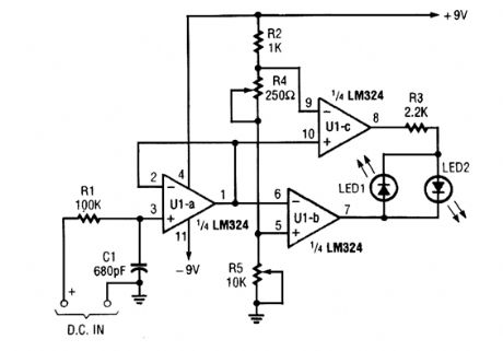
If the dc voltage is less than the voltage at pin 5 of U1-B, then LED 1 will light. If the voltage is over 5V, LED2 will light. If the voltage is within the window set by R4 and R5, neither LED will light.This circuit is useful as an under-or-over voltage monitor. (View)
View full Circuit Diagram | Comments | Reading(0)
SIMPLE_SHORT_FINDER
Published:2009/6/17 22:19:00 Author:May
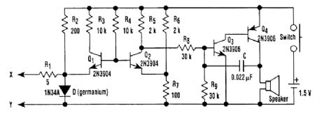
Transistors Q1 and Q2, together with resistors RI through R7, make up the input balancing stage, which senses the resistance between points X and Y. The input stage is essentially a bridge, consisting of RI, R2, R6, R7, and the resistance between points X and Y.Transistors Q3 and Q4 and their associated passive components form a buzzer, which sounds when the tester detects a short. The buzzer is controlled by the output from Q2. When the input re-sistance is high (more than about 10Ω), Q2 turns on, so its collector potential is close to ground, and the buzzer remains off. When the input resistance is sufficiently low, Q2 turns off, and the buzzer sounds. The frequency of the sound, which is about 1000 Hz, can be adjusted by varying the value of capacitor (C). (View)
View full Circuit Diagram | Comments | Reading(1099)
NE602_RF_INPUT_CIRCUITS
Published:2009/6/17 22:17:00 Author:May
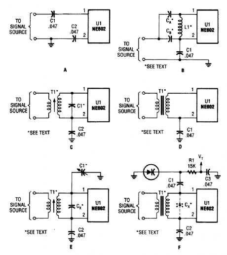
Here are a few of the many possible RE input circuits for the NE602. Just about any tuned or broadband circuit will work. (View)
View full Circuit Diagram | Comments | Reading(1217)
SHORT_TESTER_FOR_120_V_EQUIPMENT
Published:2009/6/17 22:16:00 Author:May
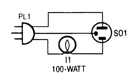
Do you deal with old equipment in unknown condition? If so, this little circuit could keep you from causing further harm to already shorted devices. (View)
View full Circuit Diagram | Comments | Reading(641)
80__AND_40_M_CW_SSB_RECEIVER
Published:2009/6/17 22:16:00 Author:May
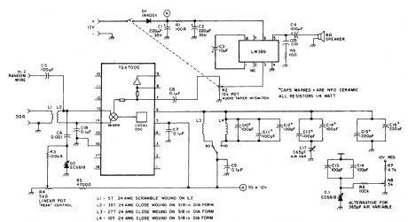
This direct-conversion receiver uses a TDA7000 IC and it drives an LM386 audio amplifier.The TDA7000 IS used forits mlxerand L.O.section. The frequency control can be either with an air variable capacitor or a varactor diode. (View)
View full Circuit Diagram | Comments | Reading(5750)
AUDIBLE_LOGIC_TESTER
Published:2009/6/17 22:16:00 Author:May
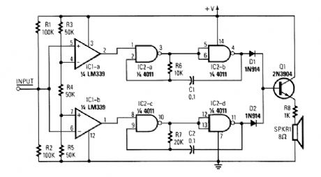
The tester provides an audible indication of the logic level of the signal presented to its input. A logic high is indicated by a high tone, a logic low is indicated by a low tone, and oscillation is indicated by an alternating tone. The input is high impedance, so it will not load down the circuit under test. It can be used to troubleshoot TTL or CMOS logic.The input section determines whether the logic level is high or low, and enables the appropriate tone generator; it consists of two sections of an LM339 quad comparator. One of the comparators (IC1-a) goes high when the input voltage exceeds 67% of the supply voltage. The other comparator goes high when the input drops below 33% of the supply. Resistors R1 and R2 ensure that neither comparator goes high when the input is floating or between the threshold levels.The tone generators consist of two gated astable multivibrators. The generator built around IC2-a and IC2-b produces the high tone. The one built around IC2-c and IC2-d produces the low tone. Two diodes, D1 and p2, isolate the tone-generator outputs, Transistor Q1 is used to drive a low-impedance speaker. (View)
View full Circuit Diagram | Comments | Reading(1122)
LINE_VOLTAGE_TO_MULTIMETER_ADAPTER
Published:2009/6/17 22:14:00 Author:May
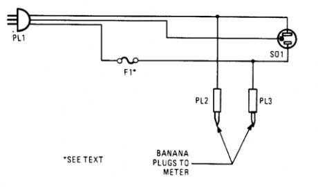
This ac line-to-ntultimeter adapter can make checking line voltage taxing loads on your household wiring. (View)
View full Circuit Diagram | Comments | Reading(652)
1_KHz_HARMONIC_DISTORTION_METER
Published:2009/6/17 22:14:00 Author:May
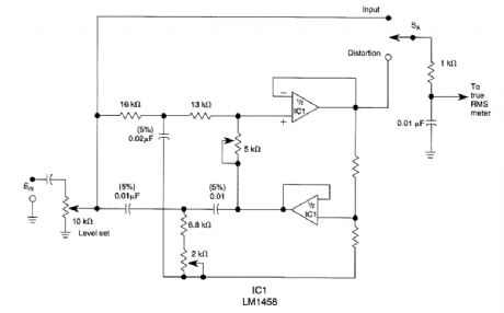
The circuit useful for distortion measurements notches out the fundamental frequency of 1 kHz to allow measurement of the residual level of harmonics. First a true BMS meter is used to measure the 1-kHz input level Ein by setting SA to the input position. Then, SA is placed in the distortion posi-tion and the 2 k potentiometer is adjusted for a null. The residual reading is noted. The THD is then calculated based on the formula: (View)
View full Circuit Diagram | Comments | Reading(1281)
NE6O2_DIRECT_CONVERSION_RECEIVER
Published:2009/6/17 22:13:00 Author:May
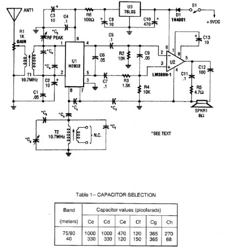
An NEC602 is used as a mixer with a zero IF frequency output. U2 acts as an audio amplifier. This receiver is primarily for SSB and CW signals. T1 and T2 are 10.7-MHz IF coils used in AM/FM transistorized radios, etc. or in any similar indicator. (View)
View full Circuit Diagram | Comments | Reading(1830)
LED_EXPANDED_SCALE_VOLTMETER
Published:2009/6/17 22:12:00 Author:May
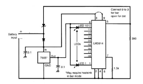
A 10-V zener diode is used to expand the scale of a 0- to 5-V voltmeter to a 10- to 15-V voltmeter.The LED bar graph lights one segment per 0.5-V input above 10 V. The 7805lC provides a 5-V reference and 5V for the bar graph LEDs. (View)
View full Circuit Diagram | Comments | Reading(1214)
S_METER_FOR_COMMUNICATIONS_RECEIVERS
Published:2009/6/17 22:12:00 Author:May
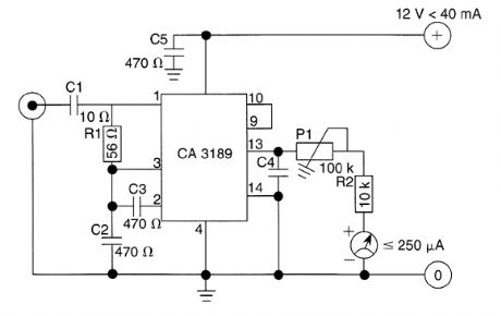
Because many amateur receivers are fitted with an S meter that functions far from logarithrnically, the proposed circuit should be a welcome extension of such receivers. Although ICs such as the CA3089 or the CA3189 are not in common use annnore, they serve a useful purpose in the meter cir-cuit, because, apart from a symmetric limiter, a coincidence detector, and an AFC amplifier, they contain a very good logarithmic amplifier-detector.As is seen, the circuit is fairly simple, but remember that these ICs operate up to about 30 MHz; the wiring of the meter and its connections in the receiver should be kept as short as possible. (View)
View full Circuit Diagram | Comments | Reading(3162)
SIMPLE_DIGITAL_LOGIC_PROBE
Published:2009/6/17 22:10:00 Author:May
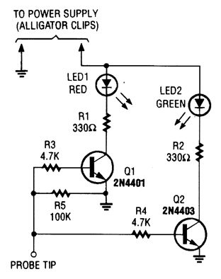
The design of the digital logic probe centers around a pair of complementary bipolar transistors, which, in this application, are used as electronic switches. (View)
View full Circuit Diagram | Comments | Reading(1065)
DVM_ADAPTER_FOR_PC
Published:2009/6/17 22:10:00 Author:May
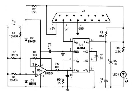
The adapter consists of a voltage to frequency adapter with a signal conditioner and protection circuit. J2 connects to the game port of a PC. See reference listed for software for use with this circuit. (View)
View full Circuit Diagram | Comments | Reading(825)
CMOS_LINE_RECEIVER
Published:2009/6/17 22:10:00 Author:May
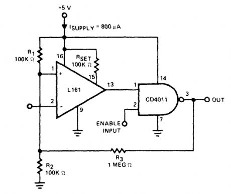
This circuit will interface a line input to CMOS. The supply current is >1 mA at +5 V. (View)
View full Circuit Diagram | Comments | Reading(0)
SIMPLE_SIGNAL_TRACER
Published:2009/6/17 22:09:00 Author:May
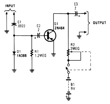
In this circuit, C1/D1/R1 form an envelope detector. C2 couples audio to the base of Q1. R2 can be adjusted for the desired gain. (View)
View full Circuit Diagram | Comments | Reading(1061)
SIGNAL_GENERATOR
Published:2009/6/17 22:08:00 Author:May
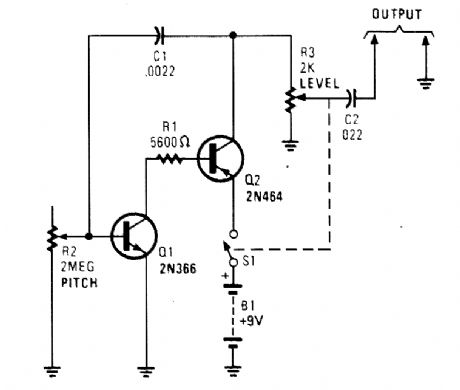
Useful for troubleshooting audio, video, and lower frequency RF amplifiers, this circuit gener-ates a signal that is rich in harmonics. (View)
View full Circuit Diagram | Comments | Reading(0)
SIMPLE_15_V_AM_BROADCAST_RECEIVER
Published:2009/6/17 22:08:00 Author:May
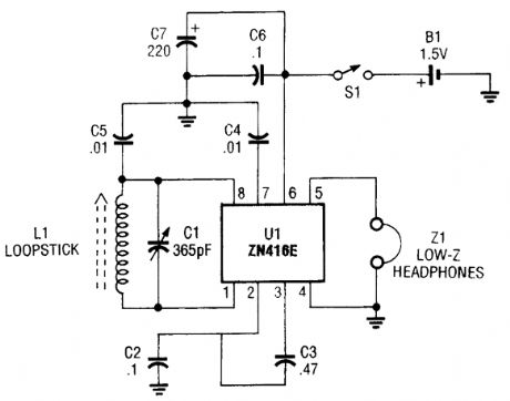
This recelver uses the ZN416E made by GEC Plessey.The tuningis via C1. (View)
View full Circuit Diagram | Comments | Reading(1167)
FAST_VIDEO_SIGNAL_AMPLITUDE_MEASURER
Published:2009/6/17 22:08:00 Author:May

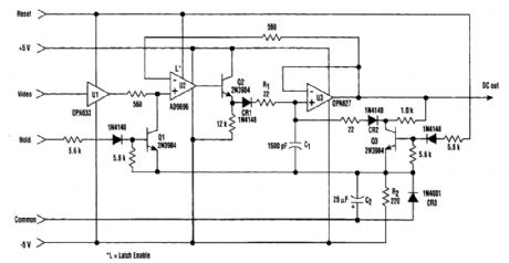
Video-signal amplitude can be measured with this simple circuit, which is basically a modified standard peak detector. The device can verify RGB generated by video RAMDACs. UI is a high-speed bttffer and U2 is a latched comparator. C1 is a hold capacitor. Reset is performed by Q3. U2 has a latch that maintains the last comparator state. The reset holds the comparator output low during the reset operation. The dc output voltage is equal to the signal's maximum amplitude. (View)
View full Circuit Diagram | Comments | Reading(821)
BASIC_AM_RECEIVER_CIRCUIT
Published:2009/6/17 22:07:00 Author:May
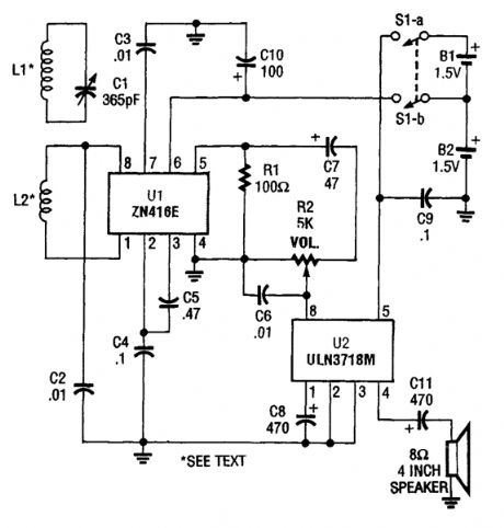
Using a single ZN416E IC and a ULN3718M, this simple TRF receiver can drive a loudspeaker Two 1.5-V cells power the circuit. (View)
View full Circuit Diagram | Comments | Reading(1512)
| Pages:1428/2234 At 2014211422142314241425142614271428142914301431143214331434143514361437143814391440Under 20 |
Circuit Categories
power supply circuit
Amplifier Circuit
Basic Circuit
LED and Light Circuit
Sensor Circuit
Signal Processing
Electrical Equipment Circuit
Control Circuit
Remote Control Circuit
A/D-D/A Converter Circuit
Audio Circuit
Measuring and Test Circuit
Communication Circuit
Computer-Related Circuit
555 Circuit
Automotive Circuit
Repairing Circuit