
Circuit Diagram
Index 1424
ISOLATED_dc_to_dc_CONVERTER
Published:2009/6/18 2:24:00 Author:May
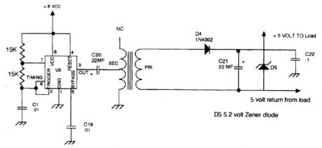

A NE555 timer is used to drive a small transformer to change the 5- to T-Vp-p output of the NE555 to a suitable value to drive a rectifier/Zener combination. This method is useful where a small isolated power source is needed. (View)
View full Circuit Diagram | Comments | Reading(3218)
MULTIPLE_FIXED_CURRENT_SOURCE
Published:2009/6/18 2:21:00 Author:May
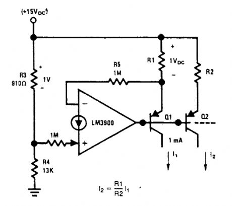


A multiple fixed current source is provided by the circuit. A reference voltage (1 Vdc) is established across resistor R3 by the resistive divider (R3 and R4). Negative feedback is used to cause the voltage drop across RI to also be 1 Vdc.This controls the emitter current of transistor Q1 and if we neglect the small current diverted into the (-) input via the 1-MQ input resistor (13.5μA) and the base current of Q1 and Q2 (an additional 2% loss if the β of these transistors is 100),essentially this same current is available out of the collector of Q1.Larger input resistors can be used to reduce current loss and a Darlington connection can be used to reduce errors caused by the β of Q1.The resistor, R2, can be used to scale the col- lector current of Q2 either above or below the 1-22-4 mA reference value. (View)
View full Circuit Diagram | Comments | Reading(1141)
WIDEBAND_PREAMP
Published:2009/6/18 2:19:00 Author:May
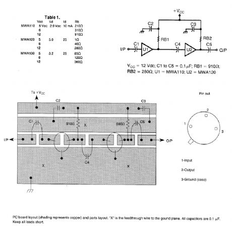
Motorola MWA 110,120,Or 130 are wideband amplifier ICs. This wideband preamp circuit can be used in many applications Keep the leads short when constructing the circuitry. (View)
View full Circuit Diagram | Comments | Reading(2107)
LC_TUNED_AMPLIFIERS
Published:2009/6/18 2:17:00 Author:May
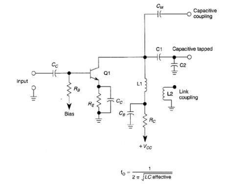
This basic tuned LC amplifier can be used with three output coupling methods. They are capac-itive coupling output, capacitive tapped output, or Iink-coupled output. (View)
View full Circuit Diagram | Comments | Reading(1369)
VOLTAGE_CONTROLLED_CURRENT_SINK
Published:2009/6/18 2:17:00 Author:May

A voltage-variable current sink is shown in the figure. The output current is 1 mA per volt of Vin(as R5 = 1 kΩ and the gain is +1). This circuit provides approximately 0 mA output current for Vin = 0 V DCL. (View)
View full Circuit Diagram | Comments | Reading(1)
5_W_7_MHz_RF_POWER_AMPLIFIER
Published:2009/6/18 2:16:00 Author:May
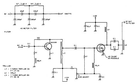
The circuit shown will produce up to 5-W RE output in the 40-m (7 MHz) amateur band. The coils shown are wound on toroidal cores (Armdon Associates Inc.). The part numbers are given in the schematic. The circuit requires about 20-mW drive and a 13-V supply. (View)
View full Circuit Diagram | Comments | Reading(781)
FOUR_STAGE_75_METER_SSB_SUPERHET_RECEIVER
Published:2009/6/18 2:12:00 Author:May
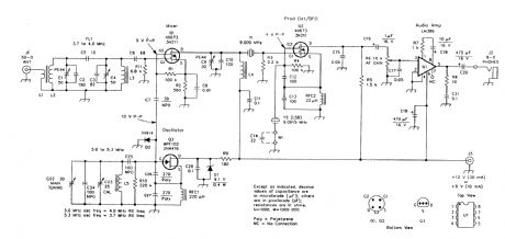
A simple superhet receiver for SSB reception in the 75-meter amateur band is shown.Y1 acts as a crystal filter. (View)
View full Circuit Diagram | Comments | Reading(3011)
VOLTAGE_CONTROLLED_CURRENT_SOURCE
Published:2009/6/18 2:12:00 Author:May

A voltage-variable current source is shown in the figure. The transconductance is-(1/R2) as the voltage gain from the input terminal to the emitter of Q1 is-1. For Vin=0Vdc, the output current is essentially 0 mA dc. Resistors R1 and R6 guarantee that the amplifier can turn OFF transistor Q1. (View)
View full Circuit Diagram | Comments | Reading(4637)
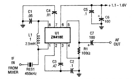
455_kHz_IF_AMP_FOR_15_V_OPERATION
Published:2009/6/18 2:11:00 Author:May
The ZN416E can be configured as a simple 455-kHz IF amplifier. In this case, the circuit's center and bandwidth are set by RES1 (a Murata CSB455E ceramic resonator). (View)
View full Circuit Diagram | Comments | Reading(1918)
SWITCHABLE_HF_VHF_ACTIVE_ANTENNA
Published:2009/6/18 2:10:00 Author:May
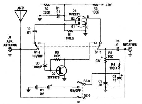
The AA-7 active antenna contains only two active elements: Q1 (an MFE201 N-channel dual-gate FET) and Q2 (a 2SC2570 npn VHF silicon transistor), which provide the basis of two indepen-dent, switchable RE preamplifiers. (View)
View full Circuit Diagram | Comments | Reading(2948)
12_kW_144_MHz_LINEAR_AMPLIFIER
Published:2009/6/18 2:09:00 Author:May
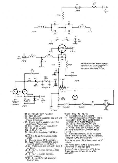
Schematic diagram ofthe 2-meter amplifier (View)
View full Circuit Diagram | Comments | Reading(958)
12_kW_144_MHz_AMPLIFIER_CONTROL_CIRCUITRY
Published:2009/6/18 2:06:00 Author:May
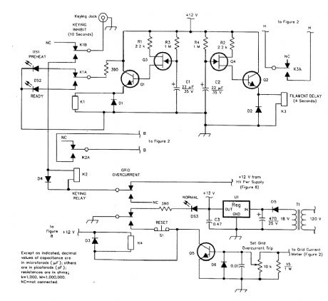
Schematic diagram of the amplifier-control circuits. (View)
View full Circuit Diagram | Comments | Reading(574)
12_kW_144_MHz_AMPLIFIER_POWER_SUPPLY
Published:2009/6/18 2:04:00 Author:May
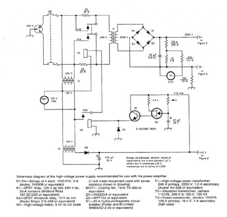
A schematic diagram of the high-voltage power supply recommended for use with the power transformer. This power supply can also be used for other equipment with similar requirements.CAUTION: hazardous high voltages. (View)
View full Circuit Diagram | Comments | Reading(1515)
HORN_CIRCUIT_FOR_MOTORCYCLE_USE
Published:2009/6/18 2:02:00 Author:May
Gates U1-a and U1-b of the 4093 quad 2-tnput NAND Schmitt trigger are connected in variable, low-frequency, square-wave oscillator circuits. The output of gate U1-a is connected to one of the inputs of gate U1-b. The square-wave output of gate U1-a modulates oscillator U1-b, producing a two-tone output. A really interesting sound can be producecl by carefully adjusting po-tentiometers R1 and R2. (View)
View full Circuit Diagram | Comments | Reading(3651)
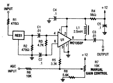
455_kHz_IF_AMPLIFIER
Published:2009/6/18 2:01:00 Author:May
Up to bU dB of gam at 455 kHz is available with the MC1350P. RES1 is a ceramic resonator, LC, or crustal filter. Keep the leads to pins,1, 2, 3, and 7 short. (View)
View full Circuit Diagram | Comments | Reading(2202)
MOTORCYCLE_BURGLAR_ALARM
Published:2009/6/18 2:00:00 Author:May
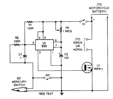
A 555 IC is connected in a one-shot timer cir-cuit that turns on a FET transistor and either a siren or the bike's horn for a preset time period. Switch S1 is used as an on/off switch.Closing either of two switches, S2 and S3, will trigger the IC. When either switch closes, pin 2 of UI goes low. That triggers the IC to produce a positive output at pin 3 and sounds the alarm for the time period set by R3. The mercury switch, S3, is the switch that activates the alarm should anyone move your bike. Switch S2 can be used as a panic switch. (View)
View full Circuit Diagram | Comments | Reading(0)
CURRENT_GENERATOR
Published:2009/6/18 1:59:00 Author:May
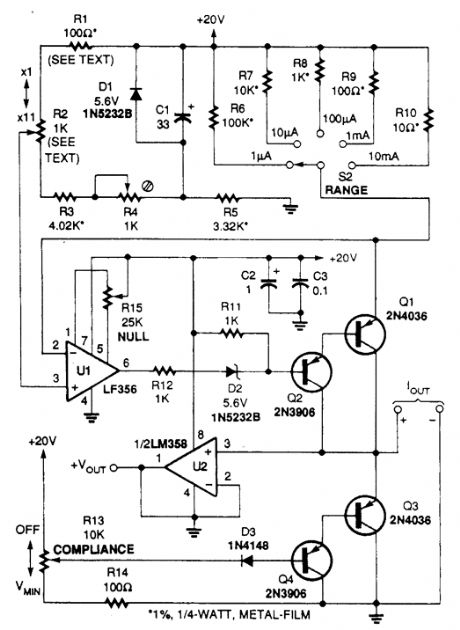
This circuit is useful for supplying constant current to test semiconductors. VOUT from U2 reads the voltage across the load connected to IOUT. R13 adjusts the supply compliance from 1 to about 18V. (View)
View full Circuit Diagram | Comments | Reading(708)
DOOR_AJAR_INDIGATOR
Published:2009/6/18 1:58:00 Author:May
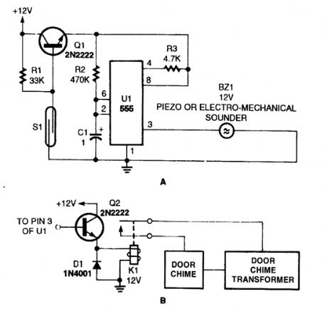
This simple sounder (AJ makes a good door annunciator. If the buzzer is replaced with the circuit in B, the annunciator can be made more pleasant to the ear.
(View)
View full Circuit Diagram | Comments | Reading(1065)
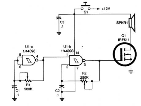
SIMPLE_BIKE_HORN
Published:2009/6/18 1:57:00 Author:May
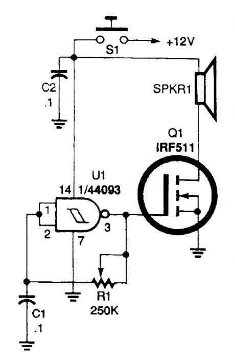
The horn circuit uses only one gate of a 4093 quad 2-input NAND Schmitt trigger, U1, con-nected in a simple, low-frequency, square-wave oscillator circuit. The oscillator's output, at pin 3, drives the gate of Q1. The drain of that FET drives a small horn speaker.Potentiometer RI can be adjusted to set the horn's output frequency. Some horn speakers are frequency sensitive, so play with the oscillator's frequency control for the best or loudest sound. (View)
View full Circuit Diagram | Comments | Reading(2069)
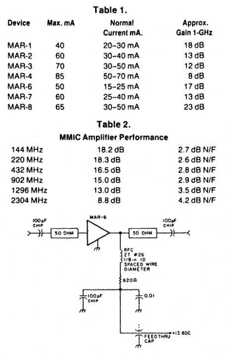
144__TO_2304_MHz_UHF_BROADBAND_AMPLIFIER
Published:2009/6/18 1:57:00 Author:May
Based on an MAR-6 preamp, this circuit yields low noise figures and useful gain for the 144-MHz to 2304-MHz amateur bands. (View)
View full Circuit Diagram | Comments | Reading(708)
| Pages:1424/2234 At 2014211422142314241425142614271428142914301431143214331434143514361437143814391440Under 20 |
Circuit Categories
power supply circuit
Amplifier Circuit
Basic Circuit
LED and Light Circuit
Sensor Circuit
Signal Processing
Electrical Equipment Circuit
Control Circuit
Remote Control Circuit
A/D-D/A Converter Circuit
Audio Circuit
Measuring and Test Circuit
Communication Circuit
Computer-Related Circuit
555 Circuit
Automotive Circuit
Repairing Circuit