
Circuit Diagram
Index 1433
ROOT_EXTRACTOR
Published:2009/6/17 3:19:00 Author:May
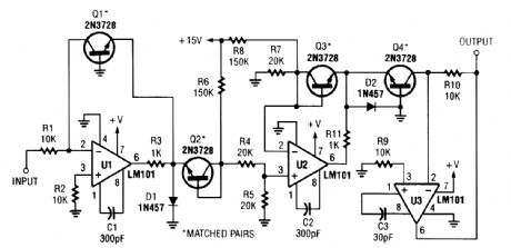
This circuit produces a voltage that is proportional to the root of the input. This gives a logarithmic response,log VINN=N log VIN. (View)
View full Circuit Diagram | Comments | Reading(1351)
LOAD_SENSING_TRIGGER
Published:2009/6/17 3:18:00 Author:May

A device plugged into S01 causes a voltage-limited gate trigger for triac TR1, and causes power to be applied to SC2. (View)
View full Circuit Diagram | Comments | Reading(1004)
LOAD_SENSING_SOLID_STATE_SWITCH
Published:2009/6/17 3:17:00 Author:May
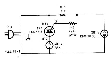
When this triac circuit senses current flow through SOl-a, it activates the device plugged into SOl-b. The values of the resistors must be chosen for the specific devices to be plugged in. (View)
View full Circuit Diagram | Comments | Reading(949)
BUFFER_ISUP2_SUPC_DATA_AND_CLOCK_LINES
Published:2009/6/17 3:15:00 Author:May
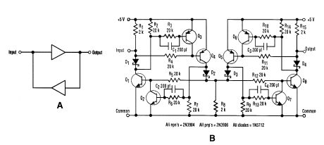
The I2C serial bus is a popular two-wire bus for small-area networks. I2C Clock and Data lines have open collector (or drain) outputs for each device on the network. Only a single pull-up resistor is needed. With this architecture, each device can talk on the network, rather than just listen. In some circumstances, it might be desirable to buffer these lines to expand the network, which can sometimes be a tricky task. The obvious approach (Fig. 1) wont work because it latches in either the higher or lower state. A circuit for a noninventory nonlatching buffer is also shown.The circuit is symmetrical about its center so that the input and output can be swapped. Q1 and Q8 are the output open collector drivers. Q2, Q3, Q6, and Q7 provide the nonlatching functions. The capacitors prevent switching glitches by ensuring the inhibit transistors tum off before the output transistors do.Operation can be best explained by example: if the input is high, Q4 turns off, and the voltage across R8 goes to zero. This tums off Q1 and Q8. The output then goes high, which is the circuit's normal resting place. If the input is pulled Iow, Q4 is tumed on.Diode D1 remains reverse-biased, preventing Q3 from tuming off Q4. With Q4 on, current is sup-plied to both Q2 and Q1 to turn them on, but Q2 turns on first to keep Q1 off. This prevents the in-put from latching. Q4 also turns on Q8. D4 is now forward-biased, so Q6 tums on, and thus tums off Q5. With Q5 off, Q7 will not tum on. The output remains low. Even with both the input and the out-put extemally driven low, the circuit will not latch. The circuit, using the values shown in Fig. 2, reached a clock rate of 80 kHz with a VOH of 5.0 V and a VOL of 0.5 V. (View)
View full Circuit Diagram | Comments | Reading(696)
PC_PASSWORD_PROTECTION
Published:2009/6/17 3:12:00 Author:May
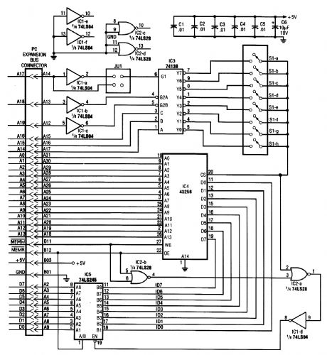
With this circuit, a PC will be protected, requiring a password to boot. After three times, the computer will have to have a cold reboot and the password tried again. Software for this system is available-consult the reference for further details. (View)
View full Circuit Diagram | Comments | Reading(1120)
TRIANGLE_AND_SQUARE_WAVE_GENERATOR
Published:2009/6/17 3:12:00 Author:May
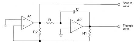
The circuit will generate precision triangle and square waves. The output amplitude of the square wave is set by the output swing of op amp A1, and R1/R2 sets the triangle amplitude. The frequency of oscillation in either case is approximately 1/0.69RC.The square wave will maintain 50% duty cycle-even if the amplitude of the oscillation is not symmetrical. The use of a fast op amp in this circuit will allow good square waves to be generated to quite high frequencies. Because the amplifier runs open-loop, corapensation is not necessary. The triangle-generating amplifier should be a compensated type. A dual op amp, such as the MC1458, can be used for most applications. (View)
View full Circuit Diagram | Comments | Reading(1971)
PRINTER_SENTRY
Published:2009/6/17 3:09:00 Author:May
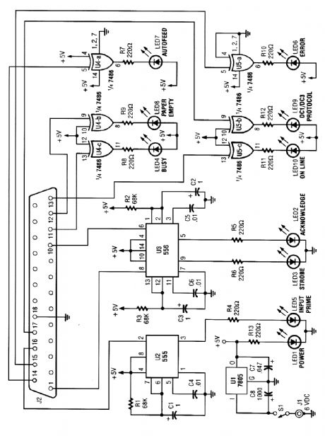
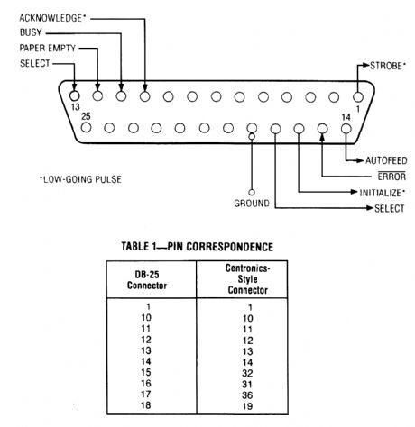
Handy for monitoring printers, this circuit displays all the signals on a parallel link. It monitors the status of the lines, enabling remote monitoring of the operation of a printer, and it also gives an indication of troubles (paper empty, busy, etc.). (View)
View full Circuit Diagram | Comments | Reading(771)
CLOCK_DRIVEN_TRIANGLE_WAVE_GENERATOR
Published:2009/6/17 3:08:00 Author:May
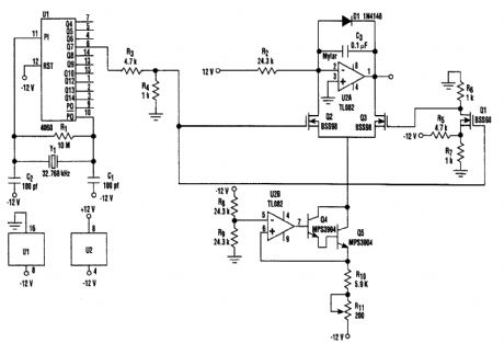
U2-a, C3 and R2 operate as an integrator. Q2 and Q3 are alternately switched at 256 cycles. U2-b, Q4, Q5, and R8 through R11 are a constant current generator, and R11 is set for a symmetrical triangular waveform. (View)
View full Circuit Diagram | Comments | Reading(1097)
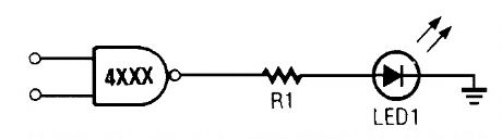
SOLID_STATE_LIGHT_SOURCES_11
Published:2009/6/17 3:07:00 Author:May
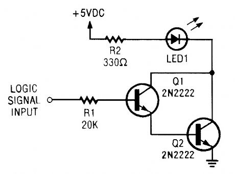
This high sensitivity Darlington LED driver circuit can be used as a simple Iogic probe. You may have to vary the value of R1 to suit the circuit under test. (View)
View full Circuit Diagram | Comments | Reading(873)
SOLID_STATE_LIGHT_SOURCES_10
Published:2009/6/17 3:06:00 Author:May
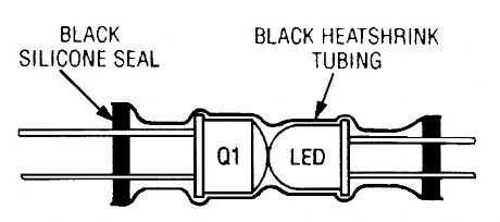
You can “roll your own” optocoupler by using some heat-shrink tubing, an LED, and optical transistor, and silicon sealant as shown here. (View)
View full Circuit Diagram | Comments | Reading(616)
SOLID_STATE_LIGHT_SOURCES_9
Published:2009/6/17 3:06:00 Author:May
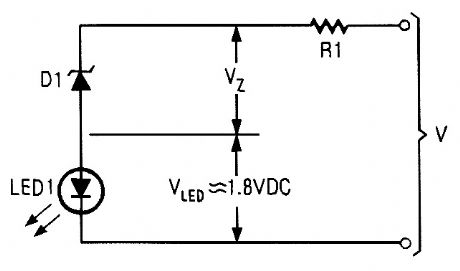
This is a simpler voltage-level sensor than that shown back in Fig. 9, To use it you have to know the polarity of the voltage it is to monitor. (View)
View full Circuit Diagram | Comments | Reading(627)
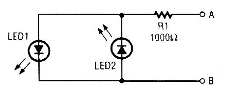
SOLID_STATE_LIGHT_SOURCES_8
Published:2009/6/17 3:05:00 Author:May
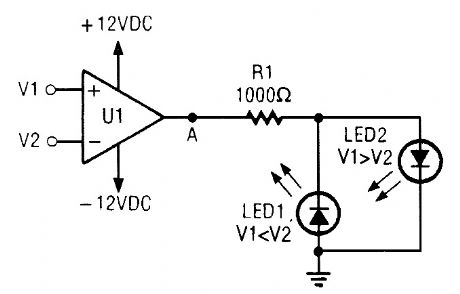
This is a bipolar output indicator that lets you know if one voltage is greater than, less than, or equal to another. (View)
View full Circuit Diagram | Comments | Reading(564)
3_CHANNEL_COLOR_ORGAN
Published:2009/6/17 3:05:00 Author:May
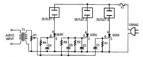
The ac line power is brought back into the circuit through F1, a protective 5-A fuse. One side of the ac line is connected to one side of each ac outlet. The other side of the ac line is connected to each SCR or silicon-controlled rectifier. Each SCR is, in turn, connected to the other side of each ac outlet.An audio signal is brought into the circuit from a stereo speaker by transformer T1. This trans-former has 500-Ω impedance on the primary and 8-Ω impedance on its secondary. Connect T1 so that the 8-Ω side is connected to the speaker and the 500-Ω side is connected to potentiometer P1.Potentiometer P1 is used as a level or sensitivity control. The signal from its wiper lead is applied to each RC filter stage. Because each SCR has a different RC (resistor/capacitor) filter on its gate lead, each will respond to different frequencies. The greater the capacitance in the filter, the lower the frequency that the SCR will respond to. (View)
View full Circuit Diagram | Comments | Reading(2322)
SOLID_STATE_LIGHT_SOURCES_7
Published:2009/6/17 3:04:00 Author:May
This simple polarity checker is easy to build and can be of help if you don't know much about a circuits wiring or grounding convention (View)
View full Circuit Diagram | Comments | Reading(580)
SOLID_STATE_LIGHT_SOURCES_6
Published:2009/6/17 3:04:00 Author:May
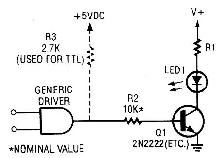
This driver circuit will work for either CMOS or TTL gates, but you don't need R3 in a CMOS-driven circuit. (View)
View full Circuit Diagram | Comments | Reading(596)
SOLID_STATE_LIGHT_SOURCES_5
Published:2009/6/17 3:03:00 Author:May
A CMOS-based gate can sink current much like a TTL gate in order to activate an LED. (View)
View full Circuit Diagram | Comments | Reading(631)
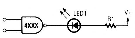
SOLID_STATE_LIGHT_SOURCES_4
Published:2009/6/17 3:03:00 Author:May
Unlike TTL devices, integrated circuits made with CMOS technology can source enough current to power an LED as shown here. (View)
View full Circuit Diagram | Comments | Reading(614)
SOLID_STATE_LIGHT_SOURCES_3
Published:2009/6/17 3:02:00 Author:May
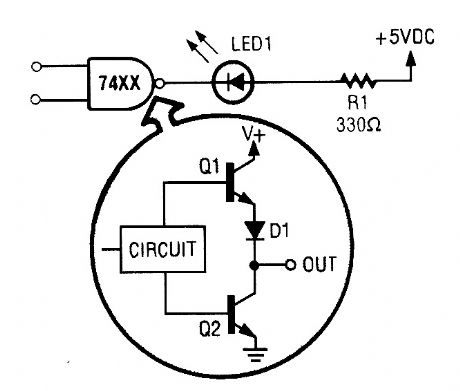
A totem-pole TTL output can drive an LED by grounding the LED's cathode, much like the open-collector driver. (View)
View full Circuit Diagram | Comments | Reading(678)
SINGLE_TRANSISTOR_CODE_PRACTICE_OSCILLATOR
Published:2009/6/17 3:01:00 Author:May
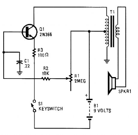
A 2N366 is configured as an audio feedback oscillator using an audio transformer is shown. Adjust R1 for proper operation and desired audio note. (View)
View full Circuit Diagram | Comments | Reading(2334)
VARIABLE_FREQUENCY_CODE_PRACTICE_OSCILLATOR
Published:2009/6/17 2:59:00 Author:May

The variable frequency audio oscillator can be used as a low-level alarm sounder or a codepractice oscillator. (View)
View full Circuit Diagram | Comments | Reading(1117)
| Pages:1433/2234 At 2014211422142314241425142614271428142914301431143214331434143514361437143814391440Under 20 |
Circuit Categories
power supply circuit
Amplifier Circuit
Basic Circuit
LED and Light Circuit
Sensor Circuit
Signal Processing
Electrical Equipment Circuit
Control Circuit
Remote Control Circuit
A/D-D/A Converter Circuit
Audio Circuit
Measuring and Test Circuit
Communication Circuit
Computer-Related Circuit
555 Circuit
Automotive Circuit
Repairing Circuit