
Control Circuit
Index 106
40_V_INPUT_5_C_10_A_DC_TO_DC_CONVERTER
Published:2009/7/13 2:23:00 Author:May
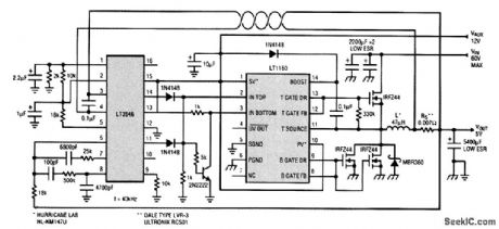
Generating 5 V at 10 A from a 40-V supply with up to 90 percent efficiency is possible using a synchronous switching regulator. The synchronous switching regulator circuit shown achieves this high efficiency by using external MOSFETs with low RDS(ON) and by shunting the Schottky diode after the topside MOSFET has completely turned off to minimize the Schottky diode's conduction losses. The LT1160 half-bridge driver alternately drives the high side and low side MOSFETs ON and OFF during switching. The loop is controlled by the LT3846 current-mode PWM controller and operates at 40 kHz. A key feature of this circuit is the ability to drive the external high-current MOSFETs safely. Internal logic in the LT1160 prevents both MOSFETs from being on at the same time, and its unique adaptive protection against shoot-through currents eliminates all matching requirements for the external MOSFETs. These protection features, in combination with the LT1160's ability to drive up to 10,000 pF of gate capacitance, make paralleling power MOSFETs for high-current applications an easy task. The high-side gate voltage is provided by a floating supply, which is boosted above the HV rail by bootstrap capacitance Cboost. An undervoltage detector in the LT1160 can sense an undervoltage condition at either the input supply or the floating supply and turn off both MOSFETs to prevent excessive power dissipation. (View)
View full Circuit Diagram | Comments | Reading(813)
OVER_1_min
Published:2009/7/13 2:14:00 Author:May
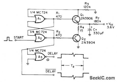
Circuit provides delays well over 1 min even with low operating voltages of ICs. When start pulse is applied to RS flip-flop A1-A2, Q2 turns off and allows RT to provide charging current for timing capacitor CT. When voltage across CT gets high enough, Q1 turns on and resets flip-flop, terminating delay period. A3 provides buffered complementary output.-R. W. Hilsher, Long-Delay Timer, EEEMagazine, Aug. 1970, p 79.
(View)
View full Circuit Diagram | Comments | Reading(864)
FET_TIMER_WITH_RELAY
Published:2009/7/13 2:12:00 Author:May
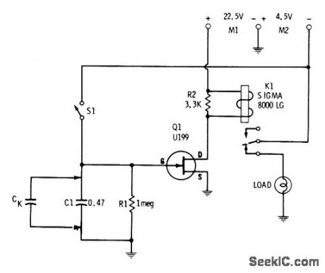
With values shown, circuit gives delay of several seconds. Increas-ing C1 bv shunting with 20-μF capacitor delays energizing of relay to over 1 min. C1 is charged to -4.5 V when switch S1 is closed, biasing gate to cutoff and deenergizing relay. When S1 is open, capacitor begins discharging at rate determined by RC time constant of circuit. When voltage across capacitordrops to point at which 01 conducts, relay is energized and power is applied to load.-E. M. Noll, FET Principles, Experiments, and Projects, Howard W. Sams, Indianapolis, IN, 2nd Ed., 1975, p 215-216. (View)
View full Circuit Diagram | Comments | Reading(1275)
SHUTDOWN_PROTECTION
Published:2009/7/13 1:52:00 Author:May
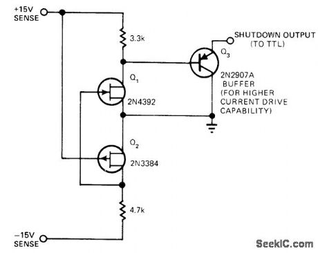
Used with digital logic to prevent generation of false logic signals when power supply is turned on or turned off, FETs sense +15 V and -15 V supplies and conduct when either supply drops below pinchoff voltage, activating shutdown output. With values shown, shutdown output is disabled when supplies exceed about 4 V, to provide normal operation.-E. Burwen, Power-Supply Monitor Suppresses False Output Signals, EDN Magazine, Nov. 5, 1977, p 110 and 112. (View)
View full Circuit Diagram | Comments | Reading(896)
FAlL_SAFE_LIGHT_TIMEB
Published:2009/7/13 1:49:00 Author:May
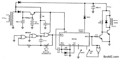
National MM5309 clock IC is used as timer in circuit that maintains timing with adequate accuracy during periods of power-line failure and retums automatically to 60-Hz line as soon as power is restored. Applications include control of lights in unoccupied home. Timing action tums on lights for 4h period every 24 h. When power is applied, intemal multiplex circuit strobes each digit until digit with connected diode is accessed. This digit stops multiplex scanning, and BCD outputs present data from selected digit as control waveform whose edges determine timer data.- MOS/LSI Databook, National Semiconductor, Santa Clara, CA, 1977, p 1.74-1-77. (View)
View full Circuit Diagram | Comments | Reading(914)
SATURATING_MVBR_ON_OFF_CONTROL
Published:2009/7/13 1:47:00 Author:May
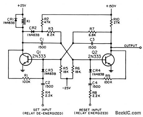
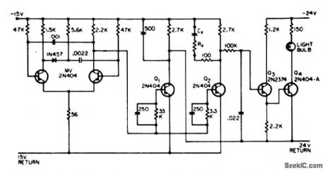
Used with relays and other electromechanical devices where current ratio must be 10 between on and off conditions. Operation is same as Eccles-Jordan, except that current drive for holding Q2 on is furnished through R2 and R3 rather than through Q1 collector load.Designed for relay that is energized by 8ma and drops out at 0.5 ma, Trigger input should be between 14 and 20V, with rise time of 10 microsec. Input circuit needs 5 millisec to recover from positive signal before next trigger is applied. 2N333 has been dropped from Preferred List, but 2N335 can be used if operating point is adjusted for its higher beta.-NBS, Handbook Preferred Circuits Navy Aeronautical Electronic Equipment, Vol, II, Semiconductor Device Circuits, PSC 17 (originally PC 251), p17-2. (View)
View full Circuit Diagram | Comments | Reading(773)
UJT_SCR_TIMER
Published:2009/7/13 1:47:00 Author:May
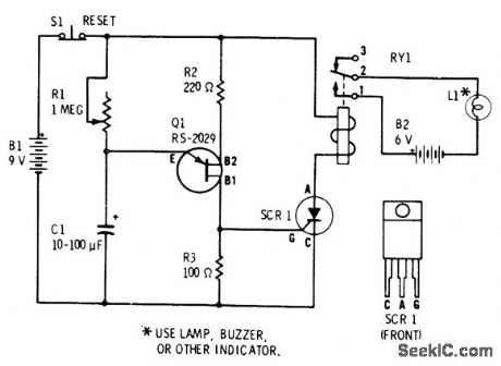
Use of large capacitance for C1 in simple UJT relaxation oscillator providestime delay action for triggering SCR controllingrelay R1 provides convenient adjustment ofdelay SCR can be 6-A 50-V Radio Shack 2761089. Relay is 275-004,-F.M.Mims, Semiconductor Projects, Vol 2, Radio Shack, Fort Worth,TX,1976,p 50-61. (View)
View full Circuit Diagram | Comments | Reading(2683)
10_s_TO_10_min
Published:2009/7/13 1:46:00 Author:May
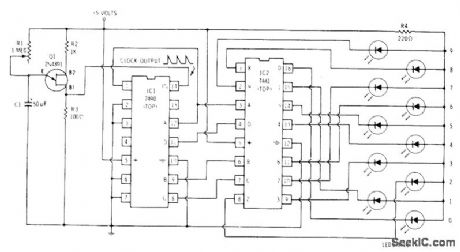
Away of ten LEDs serves for measuring time intervals up to 10 min, for timing phone calls, photographic exposures, and cooking. Pulse output rate of UJT oscillator Q1 is determined by value of C1 and setting of R1. Pulses are counted by 7490 which gives total count in binary form. 7490 recycles after each l0 counts. 7441 converts binary signals from 7490 to decimal outputs driving LED indicators. Each LED glows in sequence as count advances from 0 through 9 and repeats. For 10-pin timer, adiust R1 until first LED stays on for exactly 1 min. For 10-stimer, adiust R1 for blink rate of 1 s per LED.-F. M. Mints, Optoelectronic Proiects, Vol, n, Radio Shack, Fort Worth, TX, 1977, 2nd Ed., p 67-78. (View)
View full Circuit Diagram | Comments | Reading(872)
10_min_TIMER
Published:2009/7/13 1:35:00 Author:May
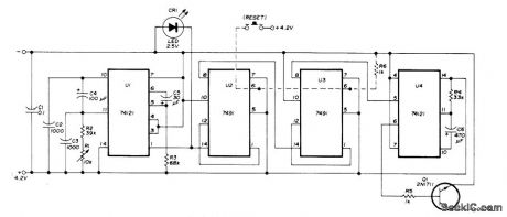
Uses SN74121 as actableMVBR generating pulses at 4-s intervals, U2 and U3 divide pulsetrain by 144 to give period of 576s U4 is then turned on, producing positive output pulse lasting 20 s that turns on Q1 for driving keyer, sidetone oscillator, lamp, or other signaling device as reminder for amateur radio operator to make 10-min station identification. R1 adjusts timing.-H. Seeger, Ten-Minute Timer, Ham Radio, Nov. 1976, p 66.
(View)
View full Circuit Diagram | Comments | Reading(1341)
Infrared automatic tap controller circuit
Published:2011/8/4 3:29:00 Author:May | Keyword: Infrared, automatic, tap controller
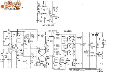
The diagram shows infrared automatic tap controller circuit. This controller circuit includes transmitting circuit and receiveing decoder control circuit. The transmitting circuit is composed of multivibratorand infrared transmitting diode; receiving circuit consists of infrared receiving tubes D1 and D2, operational amplifier IC2(CA741), tone decoder IC3(LM567), AC solid state relay IC4(SP110), power supply circuit and so on.
In the transmitting circuit, multivibrator consists of IC1(555) and R1, R2, C1, etc, and its oscillator frequency f=1.44/(R1+2R2)C1, the corresponding frequency of the parameter isshown in the picture and itis about 40KHz. Oscillator output signal can drive TLN104 LED1~LED3 work to generate infrared pulse modulated wave. (View)
View full Circuit Diagram | Comments | Reading(1641)
JET_AUTOPILOT_CONTROL
Published:2009/7/13 1:31:00 Author:May
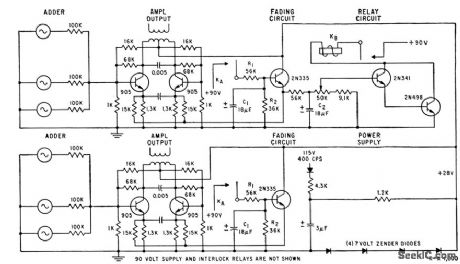
Adder-attenuator amplifier decreasos gain slowly, allowing new control modes to be set up without un-desirable aircraft motion or bumps, when jct pilot changes to different flight control mode, as from mach control to attitude control or altitude control. Relay KB allows new new mode to be set up, and output then increases to normal. When pilot operates fading switch (not shown), relay contact KA closes and 90V d-c is applied to fading circuit. Fadeout time constant is 0.5 sec and fade-in time constant 0.3 sec.-L. D. Fry, Taking the Bumps Out of Automatic Flight Control, Electronics, 32:32, p106-109. (View)
View full Circuit Diagram | Comments | Reading(889)
AUTOPILOT_GYRO_CONTROL
Published:2009/7/13 1:11:00 Author:May
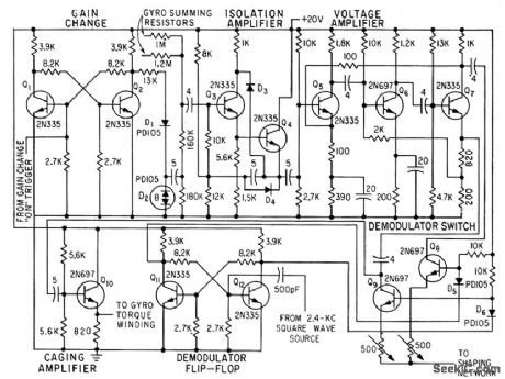
Flip-flop Q1-Q2 controls breakdown of zener diode D2. At breakdown, D2 has low impedance, shunting 180,000-ohm trigger resistor and reducing input to five-stage d-c amplifier Q3-Q7. Over-all voltage gain is 27. Demodulator is bistable lip-lop Q11-Q12 and series switching transistors Q8-Q9, giving no-signal d-c output of 9V. This level is modulated 3V for maximum in-phase or out-of-phase error signals from gyros.-J. H. Porter, Miniaturized Autopilot System for Missiles, Electronics, 33:43, p60-64. (View)
View full Circuit Diagram | Comments | Reading(1058)
NUCLEAR_REACTOR_REGULATOR_CONTROL
Published:2009/7/12 23:59:00 Author:May
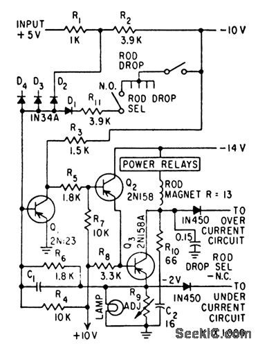
Feedback-type regulator holds magnet currents constant for control rods, at yalues set by R9 to 0.6 amp. When selected rods must be tripped for certain tests, regulator buses for these rods are connecled to -10V,to drop the rods. Ampliler uses +10V supply as reference to hold output at -2 v.-E. J.Wade and D. S. Davidson, How Transislor Circuils Protecl Alomic Reaclors, Electronics, 31:29, p73-75. (View)
View full Circuit Diagram | Comments | Reading(646)
Photo exposure timer circuit
Published:2011/8/4 3:24:00 Author:May | Keyword: Photo exposure timer
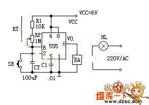
Working principle:
The photo exposure timer circuit is composed of 555 monostable circuit, which uses manually start monostable circuit. When the power is turned on, the timer will be in the steady state. At this point the voltage of the timing capacitor CT: VCT = VCC = 6V. The two inputs are in high level to this 555 equivalent trigger, that is, VS = 0. KA does not pull in, and the relay is opened, then the exposed lighting HL does not shine. This circuit provides parameters with about 1 second to 2 minutes delay time, which can be adjusted by potentiometer RP. The relay in the circuit must choose the products with the pull-in current being more than 30mA. (View)
View full Circuit Diagram | Comments | Reading(769)
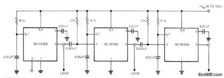
EMITTER_COUPLED_ASTABLE_LOGIC_DRIVER
Published:2009/7/16 11:23:00 Author:Jessie
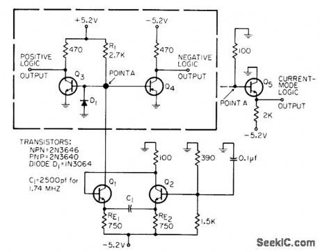
Self-starting design gives good frequency stability along with high-speed saturated positive and/or negative outputs. Current-mode logic output is optional, being obtained when circuit Q3-Q4 in dashed box is replaced by circuit of Q5. C1 determines operating frequency in range from 50 cps to 8.5 Mc.-D. R. Hoppe, Emitter-Coupled As-table With Saturated Output, EEE, 14:7, p 106. (View)
View full Circuit Diagram | Comments | Reading(956)
SCR_SWITCHING
Published:2009/7/16 10:20:00 Author:Jessie
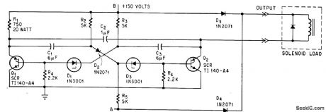
Scr's switch 0.75 amp into solenoid load at 20 cps with high reliability, simplicity, and low cost. For monostable mode, remove supply voltage form B and apply single +150-V pulse to A.-H. D. Valliant, Scr Multivibrator Switches Reliably, Electronics,38:5, p 95. (View)
View full Circuit Diagram | Comments | Reading(804)
Liquid level automatic controller circuit diagram 5
Published:2011/8/4 2:32:00 Author:Ecco | Keyword: Liquid level , automatic controller
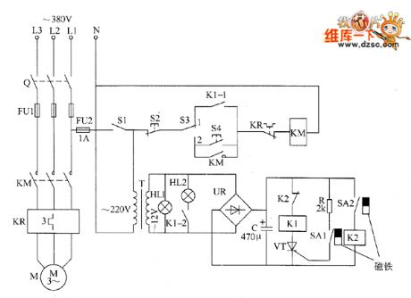
The liquid level automatic controller circuit is composed of the power supply circuit and level detection circuit control circuit, and it is shown as the chart. Power supply circuit is composed of the knife switch Q, fuses FU1, FU2, power switch S1, power transformer T, bridge rectifier UR and filter capacitor C. Liquid level detection control circuit consists of reeds SA1, SA2, relays K1, K0, thyristor VT, resistor R, AC contactor KM, thermal relay KR, control buttons S2, S4 and manual / automatic control switch S3. HL1 and HL2 are the power and working indicator lights.
(View)
View full Circuit Diagram | Comments | Reading(942)
Liquid level automatic controller circuit diagram 4
Published:2011/8/4 2:29:00 Author:Ecco | Keyword: Liquid level , automatic controller
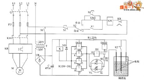
The liquid level automatic controller circuit is composed of the power supply circuit, liguid level detecting control instruction circuit, starting control circuit, and it is shown. Power supply circuit is composed of the power transformer T, bridge rectifier and filter capacitor C. Liquid detecting control instruction circuit is composed of electrodes a ~ c, six NOT gate IC (D1 ~ D6), resistors R1, R2, relay K, color light-emitting diode VL and diode VD. R1 and R2 use 1/4W carbon film resistors or metal film resistors. C selects the aluminum electrolytic capacitor with voltage in 25V.
(View)
View full Circuit Diagram | Comments | Reading(1071)
Liquid level automatic controller circuit diagram 3
Published:2011/8/4 2:23:00 Author:Ecco | Keyword: Liquid level , automatic controller
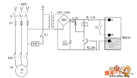
The liquid level automatic controller circuit is composed of the power supply circuit, level detection circuit and control implementation circuit, and it is shown as the chart. Power supply circuit is composed of the power transformer T, rectifier diodes YD1 ~ VD4 and filter capacitor C. Level detection circuit is composed of the high level electrode A, low level electrode B and the main electrode C. Control implementation circuit consists of the relay K, control transistor V and AC contactor KM. R1 and R2 select 1/4W carbon film resistors. C select the aluminum electrolytic capacitor with voltage in 16V. VD1 ~ VD5 use 1N4001 or 1N4007 silicon rectifier diodes.
(View)
View full Circuit Diagram | Comments | Reading(960)
IN_CIRCUIT_CAPACITOR_TESTER
Published:2009/7/16 6:06:00 Author:Jessie
Permits checking capacitors dynamically for opens or shorts without disconnecting them. Indicator light is turned on for both faults. -E. L. Major, In-Circuit Capacitor Tesler, FEE, 13;3, p 47. (View)
View full Circuit Diagram | Comments | Reading(990)
| Pages:106/312 At 20101102103104105106107108109110111112113114115116117118119120Under 20 |
Circuit Categories
power supply circuit
Amplifier Circuit
Basic Circuit
LED and Light Circuit
Sensor Circuit
Signal Processing
Electrical Equipment Circuit
Control Circuit
Remote Control Circuit
A/D-D/A Converter Circuit
Audio Circuit
Measuring and Test Circuit
Communication Circuit
Computer-Related Circuit
555 Circuit
Automotive Circuit
Repairing Circuit