
Control Circuit
Index 114
SOUND_ACTIVATED_SWITCH
Published:2009/7/10 3:08:00 Author:May
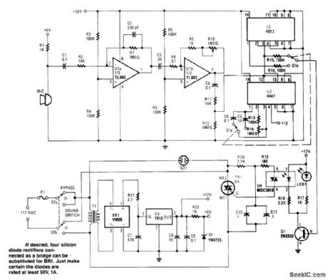
This circuit provides either latched switching or timed switching.U1A and U1B provide audio ampliftcation from the microphone,U2 is a retriggerable monostable multivibrator. S1A and S1B select either U3,a flip-flop,or U2. R13 and R14 allow a 6- to 60-second timer delay after the sound ceases,in the timed mode。BR1,U5,and associated components form a power supply.Q1 drives optocoupler U4 andtriggers triac TR1. (View)
View full Circuit Diagram | Comments | Reading(0)
VOICE_OPERATED_SWITCH
Published:2009/7/10 2:31:00 Author:May
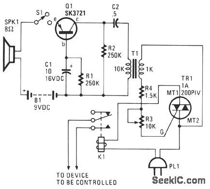
The sound picked up by SPKR1, which acts as a microphone, is fed to transistor amplifier Q1. The output of Q1 is applied across coupling transformer T1 and is used to drive the gate circuit of Triac TR1. TR1 is used to lend a latching effect to the action of the relay. (View)
View full Circuit Diagram | Comments | Reading(120)
SOUNG_ACTIVATED_SWITCH
Published:2009/7/10 2:30:00 Author:May
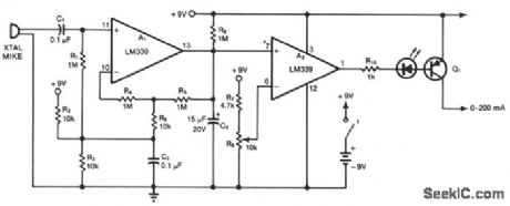


A1 and A2 are two sections of a quad comparator. The first, A1, functions as an amplifier and detector. Resistors R5 and R6 set the gain at 100; the output of A1 is an open collector to negative-peak-rectify the output with a decay time constant determined by R9 and C3. This dc output is then compared with the reference level selected by R8. A2 triggers switch Q1, and an LED inserted in the base drive of Q1 gives visual indication of switch closure. The standby battery drain is 2 mA. Use potentiometer R8 to select the desired sensitivity. (View)
View full Circuit Diagram | Comments | Reading(1029)
REMOTE_GAIN_CONTROL
Published:2009/7/10 2:12:00 Author:May
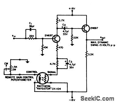
Permits adiusting gain of wideband amplifier over full range from maximum to zero with two-wire low-voltage line up to 1,000 feet long. Control and signal circuits are completely isolated.Components shown give maximum gain of l.-R. S. Young, Amplifer with Remote Gain Control, EEE, 12:8, p 71. (View)
View full Circuit Diagram | Comments | Reading(763)
CARRIER_CURRENT_TRANSMITTER
Published:2009/7/19 23:23:00 Author:Jessie
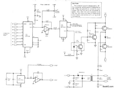
Modulates existing house wiring with high-frequency signals that can bedetected by special receivers plugged into any AC outlet, for control of appliances by home computer. Applications include turning house lights on and off during owner's absence on elaborate time schedule programmed into computer. IC1 converts 8-bit data word from computer to proportional analog output current. This is converted to voltage by IC2 for control of VCO IC3 that gives frequency proportional to voltage. With values shown, range is about 30 to 110 kHz, with 256 discrete increments of frequency. Thus, input code 00000000 gives 30 kHz, 00000001 gives 30.3 kHz, and 01000000 (decimal 64} gives 49.2 kHz. Signal is applied to house wiring by 0.5-W power amplifier Q1-Q3, using optical coupling through IC4 to prevent computer circuit from interacting with house wiring. Supply voltage ±V is 11 to 13 V. T1 is 12.6-VAC 300-mA filament transformer. ICS is 2 to 2.5 V reference chip such as MC1403U. System uses one frequency to turn receiver on and frequency 4 kHz above or below in 8-kHz band to turn it off, for maximum of ten control channels in system. Article covers calibration of transmitter.-S. Ciarcia, Tune in and Turn on, Part 1:A Computerized Wireless AC Control System, BYTE, April 1978, p 114-116, 118, 120, and 122-125 (Part 2-May 1978, p97-100 and 102).
(View)
View full Circuit Diagram | Comments | Reading(0)
Latch_circuit
Published:2009/7/19 23:22:00 Author:Jessie
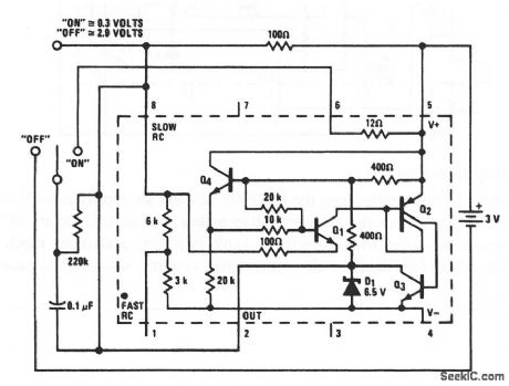
In this application, the LM3909 switches to, and holds its condition, whenever the switch changes sides-even if the contact is momentary. This results in an output that remains in the 0.3-V (on) or 2.9-V (off) condition. (View)
View full Circuit Diagram | Comments | Reading(77)
RADIO_CONTROL_FOR_MOTOR
Published:2009/7/20 1:42:00 Author:Jessie
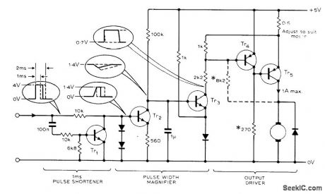
Proportional control system produces control pulses every 20 ms, with length of each adjustable between 1 and 2 ms. Circuit removes first 1 ms of pulse and expands remainder to produce 0-20 ms pulses for driving motor. Pulsing of motor gives smoother control than resistors, particularly at very low speeds. Transistor types are not critical. Tr5 can be OC28. Optional dashed connection of 8.2K resistor provides foldback current/voltage protection.-M. Weston, Variable-Speed Radio Control Motor, Wireless World, Feb. 1978, p 59. (View)
View full Circuit Diagram | Comments | Reading(851)
REMOTE_SWITCHING
Published:2009/7/20 1:41:00 Author:Jessie
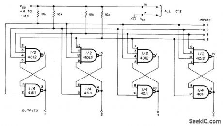
Uses four flip-flops, each having one 4-input and one 2-input CMOS NAND gate. Momentarily grounding any input drives corresponding output high and all other outputs low, Unless power is interrupted, additional pulses on same input have no effect; circuit remains stable until some other input is momentarily grounded. Outputs can be used to drive other logic devices directly or through buffer if current required exceeds 10 mA. Can be used for remote frequency control of VHF transceiver and for other applications requiring remote selection of mutually exclusive functions.-P. Shreve, Remote-Switching Circuit, Ham Radio, March 1978, p114. (View)
View full Circuit Diagram | Comments | Reading(764)
16_CHOICESWITH_3_WIRES
Published:2009/7/20 1:39:00 Author:Jessie
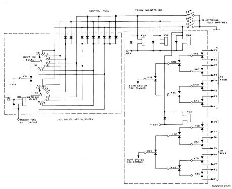
Developed for use with mobile transceiver mounted in trunk of car, to give full independent selection of eight transmit and eight receive frequencies with only three wires running to control head on dash. System involves converting 8-position switch selection in control head to 3-bit binary form for control wires, then decoding with relays. Miniature SPST relay in control head is operated by normal push-to-talk circuit to change channel selector switch when transmitting.-G. D. Rose, Independent 8-Channel Frequency Selection with Only Three Wires, QST, Aug.1974, p 36-40. (View)
View full Circuit Diagram | Comments | Reading(621)
TIMED_TONE_DECODER
Published:2009/7/20 1:37:00 Author:Jessie
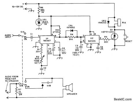
Uses NE567 PLL and 555 timer to activate muted monitoring receiver until alerting audio tone of correct frequency and duration is received. Can be applied to almost any receiver for weather emergency alert warnings, paging calls, and similar services without having to listen continously to other traffic on channel, if received tone is within bandwidth of tone decoder, output of U1 goes nearly to zero and C5 starts to discharge through R4. When voltage at pins 2 and 6 of U2 reaches one-third of supply voltage, output of U2 goes high and triggers SCRQ1, energizing 12-V relay K1. Values shown for C4 and C5 give 1-s delay, which means triggering tone must be on at least 1 s. Once SCR is triggered, it holds relay on even after tone ceases. Pushbutton switch shorts SCR and releases relay when reset is desired. Zener provides regulated 6.2 V required for decoder. Values shown for R1, R2, and C2 give response to 450-Hz tone. Avoid use of Touch-Tone frequency, to prevent accidental triggering by those using Touch-Tone system.-J. S. Paquette, A Time-Delayed Tone Decoder, QST; Feb. 1977, p 16-17. (View)
View full Circuit Diagram | Comments | Reading(964)
CARRIER_CURRENT_RECEIVER
Published:2009/7/20 1:33:00 Author:Jessie
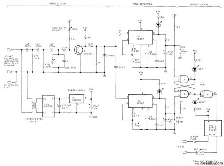
When it is plugged into AC line, receiver responds to pair of control frequencies 4 kHz apart in range of 30 to 110 kHz, placed on house wiring by computer-controlled transmitter, Receiver turns controlled device on or off through solid-state relay for which article gives suitable circuit, Tuned bandpass filter amplifies only that pair of frequencies assigned to its receiver, attenuating all other frequency pairs used in system.Amplified signal is sent to tone decoders IC1 and IC2, one responding to each frequency.Input filter provides attenuation of 60-Hz line frequency and all other frequencies except 8-kHz band of specific channel. LC bandpass circuit, set for center of desired passband, acts as passive filter. L is low-Q slug-tuned 1-10 mH coil, set at 2 mH when C is made 0.01μF for center frequency of 35 kHz. Article covers operation in detail and gives procedure for determining values of R1, C1, and 02 for each detector. Solid-state output relay can be Sigma 226 RE1-5A1, rated 6 A.-S. Ciarcia, Tune in and Turn on, Part 2:An AC Wireless Remote Control System, BYTE. May 1978,p97-100 and 102(Part 1- April 1978,p114-116,118,120,and 122-125). (View)
View full Circuit Diagram | Comments | Reading(0)
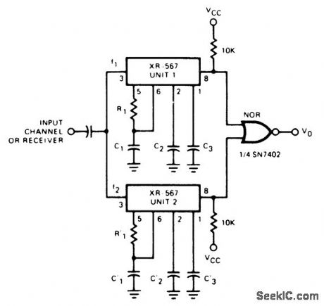
DUAL_TIME_CONSTANT_TONE_DECODER
Published:2009/7/20 1:31:00 Author:Jessie
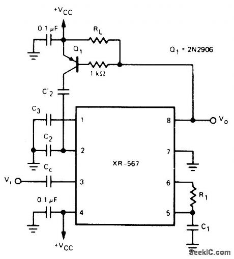
Exar XR-567 PLL system is connected as de-coder having narrow bandwidth and fast response time. Circuit has two low-pass loop filter capacitors,C2 and C'2. With no input, pin 8 is high,Q1 is off, and C'2 is out of circuit. Filter then has only C2, which is kept small for minimum response time. When in-band input tone signal is detected, pin 8 goes low, Q1 turns on, and C'2 is in parallel with C2 to give narrow bandwidth. Supply voltage can be 5-9 V.- Phase-Locked Loop Data Book, Exar Integrated Systems, Sunnyvale, CA, 1978, p 41-48. (View)
View full Circuit Diagram | Comments | Reading(1537)
DUAL_TONE_DECODER
Published:2009/7/20 1:29:00 Author:Jessie
Used in communication systems where control or other information is transmitted as two simultaneous but separate tones Circuit uses two Exar XR-567 PLL units in parallel, with resistor and capacitor values of each PLL decoder selected to provide desired center frequencies and bandwidth requirements supply voltage is 5-9V.- Phase-Locked Loop Data Book. Exar Integrated systems,Sunnyvale,CA,1978,p41-48. (View)
View full Circuit Diagram | Comments | Reading(1606)
RESISTANCE_TRIGG_FRED_ALARM
Published:2009/7/10 1:26:00 Author:May

Silicon controlled switch is triggered when temperature-, light-, or radication-sensifive resistor Rs up to meter drops below vadue of preset potentiometer.Interchanging Rs and potentiometer will trigger alarm on increase in sensing resistor.- Transi stor Manual, Seventh Edition, General Electric Co., 1964, p 425. (View)
View full Circuit Diagram | Comments | Reading(1066)
LIGHT_BEAM_FOR_CONTROL_OF_MOVING_TOY
Published:2009/7/19 23:32:00 Author:Jessie
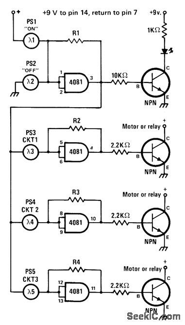
Battery-powered CM0S logic is switched on and off by aiming flashlight beam at photocell, for turning small motors of model train or other powered toy on and off. Transistors can be 2N2222A for most small motors, but larger motors will require power transistors, Use high-intensity flashlight, with shield over lens to restrict beam width, so only one of five photocells is illuminated at a time. LED shows ON/OFF status of circuit. Values of R1-R4 are chosen so each gate flips logic state only when associated photocell is illuminated.-J. Sandler, 9 Projects under $9, Modern Electronics, Sept. 1978, p 35-39. (View)
View full Circuit Diagram | Comments | Reading(886)
8_CHOICES_WITH_3_WIRES
Published:2009/7/19 23:30:00 Author:Jessie
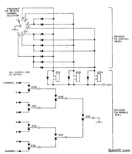
Provides remotely selected choice of eight functions, such as channels in mobile FM station, with only three wires running from control head to controlled equipment that can be in front of car. System involves converting 8-position switch selection in control head to 3-bit binary form for three control wires going to three-relay arrangement for decoding back to 8-position format. Relays are two-pole and four-pole double-throw 12-V units.-G. D. Rose, Independent 8-Channel Frequency Selection with Only Three Wires, QST, Aug. 1974, p 36-40. (View)
View full Circuit Diagram | Comments | Reading(662)
NINE_CHANNEL_DECODER
Published:2009/7/19 23:29:00 Author:Jessie
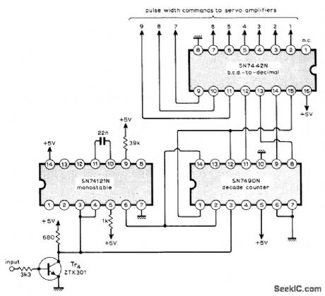
Circuit accepts serial information arriving over data link as series of nine varying-width pulses followed by fixed-width sync pulse, and after detection passes the nine individual commands to their respective servoamplifiers. Use of TTL ICs gives low component count for remote control system. Detection of sync pulse is done by comparing length of inverted input pulses with output of 0.6-ms monostable reference. All command pulses exceed 0.6 ms, so only 0.5-ms sync pulse clears counter to prepare for next channel-1 command pulse. Article gives operating details of system and circuits for coder and servoamplifier.-M.F. Bessant, Multi-Channel Proportional Remote Control, Wireless World, 0ct. 1973, p 479-482. (View)
View full Circuit Diagram | Comments | Reading(1141)
LAMP_CONTROL_WITHOUT_CONDUIT
Published:2009/7/20 1:48:00 Author:Jessie
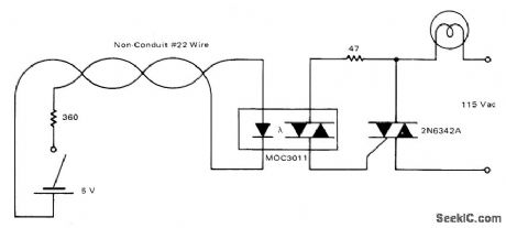
Motorola M0C3011 optoisolator permits control of large lamp,motor, pool pump, and other AC loads from remote location with low-voltage signal wiring while meeting building codes. Choice of triac depends on load being handled.-P.O'Neil, Applications of the MOC3011 Triac Driver, Motorola, Phoenix, AZ, 1978, AN-780, p 5. (View)
View full Circuit Diagram | Comments | Reading(1583)
ON_OFF_CONTROL_BY_THREE_TONES
Published:2009/7/20 1:46:00 Author:Jessie
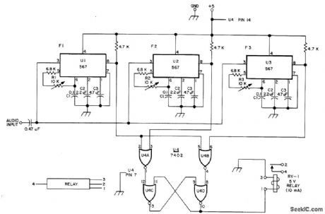
Used for decoding two Touch-Tone digits to give operation or release of relay by remote control over wire line. Three 567 tone decoders and 7402 quad gate are adjusted to recognize tones corresponding to any two keys in given row or column on Touch-Tone keyboard. As example, * key generates 941 and 1209 Hz, and circuit can be adjusted so these two frequencies energize relay. Similarly, pushing of # key generates 941 and 1477 Hz that can be used for deenergizing relay.-W. J. Hosking, Simple New TT Decoder, 73 Magazine, April 1976, p 52-53. (View)
View full Circuit Diagram | Comments | Reading(1494)
NINE_CHANNEL_CODER
Published:2009/7/20 1:45:00 Author:Jessie
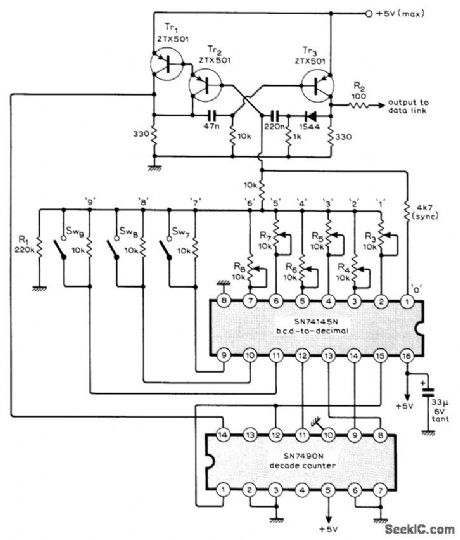
Use of 'Ff L ICs gives low component count for remote control sys-tem having nine fully proportional channels. Input channels can be potentiometers for fully proportional information and switched resistors for go/no-go or multistep information.Coder scans the nine parallel inputs sequentially and presents them to single-line data link as series of nine varying-width pulses followed by fixed-width sync pulse. Article describes coder operation in detail and gives circuits for corresponding decoder and servoamplifier at receiving end of data link.-M. F. Bessant, Multi-Channel Proportional Remote Control, Wireless World, Oct. 1973, p 479-482. (View)
View full Circuit Diagram | Comments | Reading(842)
| Pages:114/312 At 20101102103104105106107108109110111112113114115116117118119120Under 20 |
Circuit Categories
power supply circuit
Amplifier Circuit
Basic Circuit
LED and Light Circuit
Sensor Circuit
Signal Processing
Electrical Equipment Circuit
Control Circuit
Remote Control Circuit
A/D-D/A Converter Circuit
Audio Circuit
Measuring and Test Circuit
Communication Circuit
Computer-Related Circuit
555 Circuit
Automotive Circuit
Repairing Circuit