
Control Circuit
Index 115
WIRELESS_CONTROL
Published:2009/7/20 1:44:00 Author:Jessie
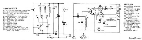
Choice of three lamps or appliances anywhere in house and garage, or even in neighboring home if on the same power transformer, can be turned on or off individually with three-channel transmitter that plugs into any wall outlet. Transmitter injects one of three tones (depending on button pushed) into house wiring. Receivers at locations of controlled de-vices are each tuned to one of carrier tones. Correct tone for receiver energizes neon lamp, and resulting light is picked up by photo resistor that energizes latching relay K for turning on controlled device. Relay is released by sending same tone again. Values of CX can be 0.005, 0.01, and 0.02μF, Adjust slug of L2 for each receiver so neon comes on when assigned tone for that receiver arrives.-W. J. Hawkins, Three-Channel Wireless Switch-Use It Anywhere, Popular Science, Sept. 1973, p 98-99 and 121. (View)
View full Circuit Diagram | Comments | Reading(895)
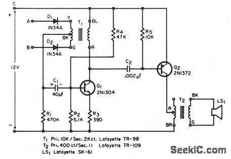
LAMP_BURNOUT_ALARM
Published:2009/7/9 23:49:00 Author:May
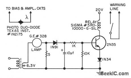
Used when photocells and lamps are employed to detect end of magnetic tape, lood point, or bad spot.Failure of lamp can cause serious trouble in magnetic tape handler. With circuit showm, when lamp burns out, transistor can no longer energize relay, and relay contact doses to actuate alarm at computer console.-J. E. Kienle and R. W. Wooldridge, Photocell Lamp Burnout Warning Circuit, EEE, 10:8, p 27-28. (View)
View full Circuit Diagram | Comments | Reading(924)
MULTIPLE_INPUT_ALARM
Published:2009/7/9 23:44:00 Author:May
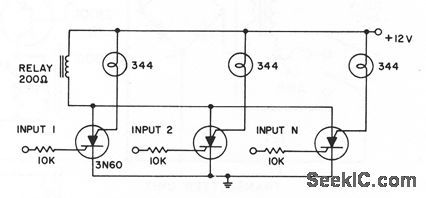
Any of several inputs will pull in common alarm relay, with corresponding lamp giving visual indication of triggered circuit. For higher-current laps, use 3N81 silicon controlled swilches.- Iransistor Manual, Seventh Edition, General Electric Co., 1964, p 425.
(View)
View full Circuit Diagram | Comments | Reading(1053)
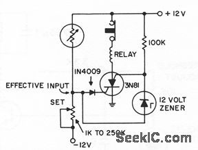
GYRO_FAULT_ALARM
Published:2009/7/9 23:40:00 Author:May
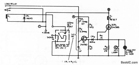
Circuit sounds alarm if gyro wheel is locked up, as indicated by input signed remaining at high current or voltage level for longer than preset interval.Circuit can also be used as pulse-level discrimincttor.-R. L. Sazpansky, Pulse-Level Discriminator and Fault Indicator, EEE, 13:8, p 68. (View)
View full Circuit Diagram | Comments | Reading(985)
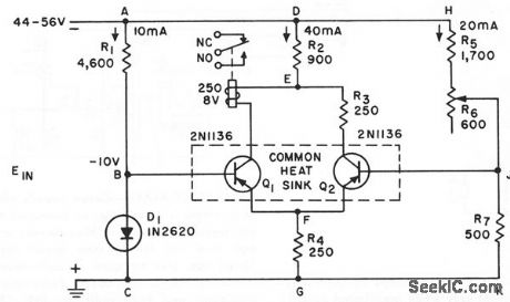
DIFFERENTIA_L_VOLTAGE_ALARM
Published:2009/7/9 23:39:00 Author:May
Deleclor circuit with high sensitivity and stability, followed by audio ampliler, serves as differential voltage or current alarm. Input may be d-c or low-frequency a-c. Output is distinctive series of audio beeps or continuous tone, occurring only when preselected polarity unbalance is present at input.-C. E. Miller, Differentktl-Voltage or Current Alarm Circuit, EEE, 12:7, p 25. (View)
View full Circuit Diagram | Comments | Reading(942)
INFRARED_BURGLAR_ALARM
Published:2009/7/9 23:37:00 Author:May
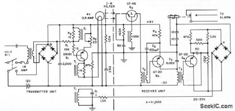
Has electronically modulated infrared light source and synchronous phase sensitive demodulator pick up unit. Pulsed-light technique overcomes adverse effects of continuous or varying ambient light.Alarm goes off if power supply or interconnecting wires are tampered with.Floating 12-v battery takes over load only if power supply fails.C1 tunes T1 to 55-cps oscillator frepuency.-S.Bagno and J.Fasal,Intruder Alarm Uses Phase-Sensitive Detector,Electronics,31:7,p 102-105.
(View)
View full Circuit Diagram | Comments | Reading(1033)
VOLTAGE_SENSING_ALARM
Published:2009/7/9 23:36:00 Author:May
Silicon controlled switch is triggered by input signal more than 1 v above or below ground.- Transistor Manucal, Seventh Edition, General Electric Co., 1964, p 425. (View)
View full Circuit Diagram | Comments | Reading(783)
POSITIVE_UMIT_ALARM
Published:2009/7/9 23:34:00 Author:May
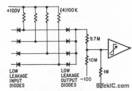
Operafional trigger trips when any output of analog computer goes off scale (above +99 v).-P. Lefferts, Operationctl Trigger For Predse Control, Electronics, 37:28, p 50-55. (View)
View full Circuit Diagram | Comments | Reading(741)
LOW_VOLTAGE_ALARM
Published:2009/7/9 23:34:00 Author:May
Two-transistor alarm senses 0.2-v drop in telephone system und turns on loctd or remote signalling apparatus.If relay and R3 are interchcnged, circuit will opera as high-voltage alarm,-C.J. Kieffer,Simple Low-Voltage Alarm,Electronics,35:18,p 44-45. (View)
View full Circuit Diagram | Comments | Reading(288)
STEERABLE_ANTENNA_CONTROL
Published:2009/7/20 2:45:00 Author:Jessie
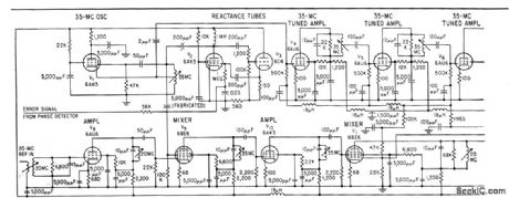
Phase-stabilized 35-Mc uhf amplifier controls directivity of multi-element stationary antenna array. Phase of amplifier output is compared with input reference signal in phase-sensitive detector. System keeps input-output error under 2°.-E. W. Markow, Servo Phase Control Shapes Antenna Pattern, Electronics, 32:1, p 50-52. (View)
View full Circuit Diagram | Comments | Reading(1330)
ONE_ZENER_PRECISE_LIMITER
Published:2009/7/9 23:32:00 Author:May
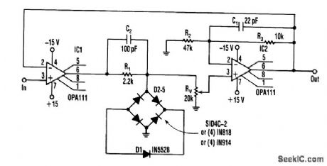
A limiter circuit that requires matched zener diodes can instead use one zener with a full-wave diode bridge. The circuit's two limits are nearly equal when determined by the same zener-only two pairs of forward diodes need to be matched. For best results, an integrated quad of diodes can be used. But, after testing the circuit, four single controlled-drop diodes and four ordinary diodes gave about the same accu-racy (better than 0.5%).
Because the limiting level can be adjusted, zener tolerance can be adjusted out. Gain stability can be optimized by connecting the inverting input to the first op amp to the output of the second to make the circuit inherently unity-gain.
The zener voltage must be increased to 8.2V to compensate for the two diode drops. Placing small capacitors across the resistors in the loop stabilized the circuit adequately and response is orders of magni-tude faster than conventional circuits. Moreover, it's limited primarily by the op amp's slew rate. (View)
View full Circuit Diagram | Comments | Reading(2559)
SHORT_CIRCUIT_ALARM
Published:2009/7/9 23:32:00 Author:May
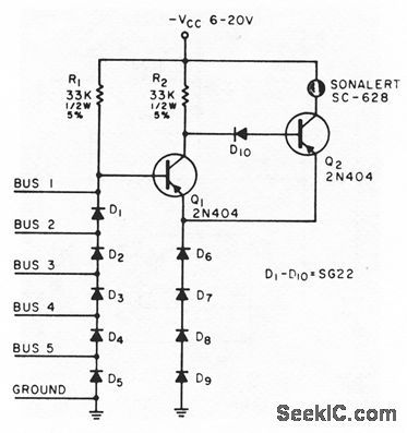
Sounds an alarm if a short occurs between any two of five different voltage buses or between any bus and ground.Used in checking complicted point-to point backplane wiring for computers,to detect wiring errors or solder splashes.-J.J.Russo,Short-Circuit Alarm,EEE,13:6,p 66-68. (View)
View full Circuit Diagram | Comments | Reading(882)
ADF_PHASEMETER
Published:2009/7/20 2:25:00 Author:Jessie

Input signals are squared by Schmitt triggers, differentiated, and changed to unidirectional pulses that drive flip-flop V4 to produce pulse whose length is proportional to bearing of transmitter. 500-cps signal from phonic wheel is sharpened by Schmitt trigger V7 and used to indicate length of bearing pulse in degrees by modulating the pulse in V6. One output goes to decade counter chain that counts total number of degrees.-J. F. Hatch and D. W. G. Byatt, Direction Finder with Automatic Readout, Electronics, 32:16, p 62-64. (View)
View full Circuit Diagram | Comments | Reading(760)
STEPPER_MOTOR_DRIVER
Published:2009/7/20 2:24:00 Author:Jessie
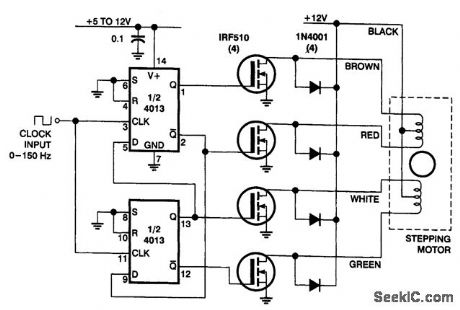
In this circuit, four IRF510 power FETs are driven by a CMOS counter to generate the necessary two-phase drive quadrature. Although ICs are available to do this, this approach is handy for the experimenter because it uses commonly available parts. The stepper motor was taken from a discarded floppy-disk drive. (View)
View full Circuit Diagram | Comments | Reading(8182)
6_VARISTOR_PHASE_SHIFT_VTO
Published:2009/7/20 2:22:00 Author:Jessie
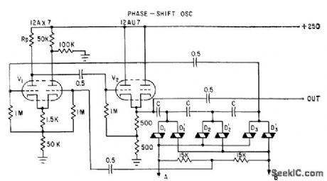
Range is ten times lowest frequency, with upper limit of several kc, depending on values of C. Triode differential amplifier V1 is first stage of oscillator. One input grid, for a-c amplification, goes to output of phase-shift circuit. Other grid goes to centertap across SiC varistors. -M. Uno, Varistor Network Controls Voltage-Tuned Oscillator, Electronics, 34:30, p 44-47. (View)
View full Circuit Diagram | Comments | Reading(675)
MULTIPLE_INPUT__OVERVOLTAGE__ALARM
Published:2009/7/9 23:27:00 Author:May
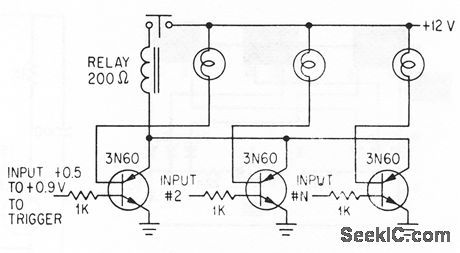
Lamp load of each silicon-contralled switch lights when its input exceeds threshold voliage,to identify input that is responsible for pulling In relay that sounds alarm or shutsdown equipment Lamps aIso serve to suppress rate effect-R.A.Stasior How to suppress Rale Effect in PNPN Devices,Electronics,37:2, p 30-33. (View)
View full Circuit Diagram | Comments | Reading(882)
VHF_INTRUSION_ALARM
Published:2009/7/9 23:25:00 Author:May
Based on fact that object moving toward or away from antenna causes phase relationship of radiated and reflected waves to shift through 2 pi radians at antenna for each half-wave length of movement. Varying phase changes amplitude of oscillation, detected by circuit and used to turn on alarm. Drift in oscillator grid voltage activates timing motor which adjusts degree of coupling between oscillator tank and antenna, to make alarm self-adjusting.-G. A.Whitlow, VHF Intrusion Alarm is Self-Adiusting, Electronics, 3235, p 62-66. (View)
View full Circuit Diagram | Comments | Reading(742)
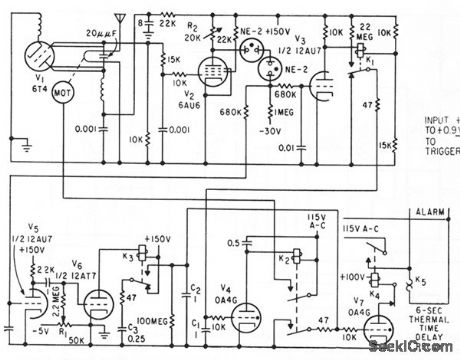
COMPUTER_FAULT_ALARM
Published:2009/7/9 23:22:00 Author:May
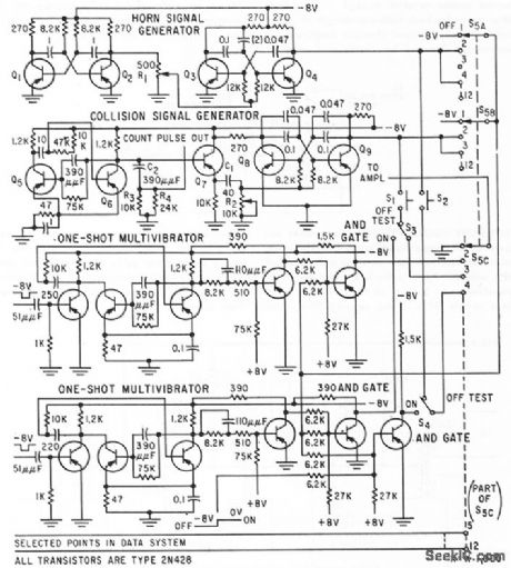
AudibIe alarm system gives distinctive indication of fault loccttion in digitcd computer and data processing equipment. Hom cnd collision signcd sounds are generctted by electronic circuits shown, for monitoring two circuits. Mixing those two signals produces battle stations sound for monitoring third circuit.-S. Fierston, Alarm Circuit Warns of Faults in Digital Systems, Electronics, 32:27, p 48-49. (View)
View full Circuit Diagram | Comments | Reading(843)
FAULT_SENSING_SWITCH
Published:2009/7/9 23:19:00 Author:May
When fault in microwave system has effect of closing switch 3, gated delcty shortens output pulse for that function when binary input signals are negative.-J. B. Bullock, Pulse-Coded Fault Alarm in Microwave Systems, Electronics, 33:1, p 82-84. (View)
View full Circuit Diagram | Comments | Reading(822)
FLIP_FLOP_DEBOUNCER_SWITCH
Published:2009/7/9 23:19:00 Author:May
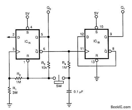
Although this circuit uses a 74HC74, any CMOS variant of this flip-flop will work. IC1A acts as a true/ complement buffer. RI and R2 ensure that IC1A comes out of reset before the clock's edge occurs. R3 applies IC1A's logic state to pins 1 and 3. When the switch closes, the next logic state stored on the capaci-tor transfers to the flip-flop's reset and clock inputs. Releasing the switch lets the capacitor charge to the next state via R4. IC1A's output is the LSB; IC1B's output is the MSB.
Notice that the counter's state advances when the switch is first pressed, rather than when it's released; the latter is the case with many other switch-debouncing schemes. lbu can replace RI with a 22-pF capacitor to reduce the circuit's sensitivity to parasitic effects. The addition of this capacitor also lets you !ower the magnitude of R2 and R3 by a factor of 10. (View)
View full Circuit Diagram | Comments | Reading(3199)
| Pages:115/312 At 20101102103104105106107108109110111112113114115116117118119120Under 20 |
Circuit Categories
power supply circuit
Amplifier Circuit
Basic Circuit
LED and Light Circuit
Sensor Circuit
Signal Processing
Electrical Equipment Circuit
Control Circuit
Remote Control Circuit
A/D-D/A Converter Circuit
Audio Circuit
Measuring and Test Circuit
Communication Circuit
Computer-Related Circuit
555 Circuit
Automotive Circuit
Repairing Circuit