
Control Circuit
Index 107
BODY_CAPACITANCE_ALARM
Published:2009/7/16 6:03:00 Author:Jessie
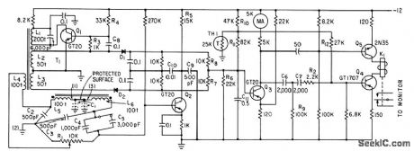
Detects intruder by sensing body capacitance. Oscillator Q1 feeds 20 kc to capacitance bridge that contains C1, which is capacitance to ground of protected cabinet. When unbalanced, bridge feeds 20-kc signal to amplifier Q2, whose output goes to phase-sensitive detector D1-D2, which converts unbalance signal into d-c voltage for amplification by Q3. At balance, Q4 and Q5 send about I ma through relay K1 to keep it energized. When intruder approaches protected cabinet, output of phase-sensitive detector becomes more negative, causing K1 to drop out and sound an alarm.-S. M. Bagno, Sensitive Capacitance Intruder Alarm, Electronics, 33:38, p 65-67. (View)
View full Circuit Diagram | Comments | Reading(923)
ANEROID_DRIVEN_CAPACITOR
Published:2009/7/16 6:02:00 Author:Jessie
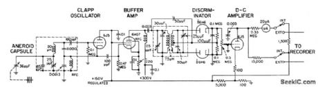
Datum stabilizer for radar-altimeter surveying uses oscillator to produce output current proportional to change in altitude. Resonant frequency of high-stability 3.5-Mc oscillator is varied by small capacitor plate driven by three-element aneroid. Discriminator and d-c amplifier transform resulting frequency changes to current variations proportional to changes in height.-J. Markus and V. Zeluff, Handbook of Industrial Electronic Control Circuits, McGraw-Hill, N.Y., 1956, p 23.
(View)
View full Circuit Diagram | Comments | Reading(805)
INTRUSION_ALARM
Published:2009/7/16 6:00:00 Author:Jessie
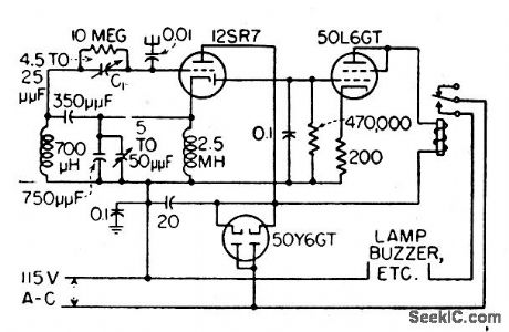
Circuit stops oscillating when intruder approaches antenna surrounding area being protected. Uses weak oscillator with relay tube that is biased to cutoff by some of oscillator output. Additional capacitance caused by intruder stops oscillator, removing bias and making tube conduct and actuate relay to sound alarm.-J. Markus and V. Zeluft, Handbook of Industrial Electronic Control Circuits, McGraw-Hill, N.Y., 1956, p 19. (View)
View full Circuit Diagram | Comments | Reading(706)
CAPACITANCE_TRANSDUCER_FOR_30000_RPM_IACHOMETER
Published:2009/7/16 5:57:00 Author:Jessie
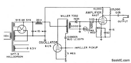
R-f oscillator is adjusted to oscillator feebly anywhere between 500 and 2,000 kc. When pickup capacitance increases, it shunts oscillator feedback circuit more, reducing its r-f output voltage. Resulting drop in a-c component of rectified r-f carrier is amplified to drive tachometer or frequency meter. Pickup is mounted close to moving blades on shaft whose speed is being measured.-J. Markus and V. Zeluff, Handbook of Industrial Electronic Control Circuits, McGraw-Hill, N.Y., 1956, p 17. (View)
View full Circuit Diagram | Comments | Reading(678)
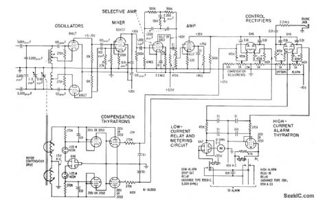
MONITORING_ENAMEL_THICKNESS_ON_WIRE
Published:2009/7/16 5:55:00 Author:Jessie
Wire is run through mercury-filled vessel. Bridge output goes to pair of mixer tubes (6AJ8 is U.S. equivalent) whose plate circuits form d-c vtvm, with milliammeter indicating amount of bridge unbalance. Bridge is formed by connecting mercury vessel, grounded wire, fixed capacitor, and variable capacitor to secondary coil of differential transformer.-Monitor Wire Enamel by Capacitance Bridge, Electronics, 33:44, p 92-97. (View)
View full Circuit Diagram | Comments | Reading(714)
CONTROLLING_EXTRUSION_OF_PLASTIC_ON_WIRE
Published:2009/7/16 5:54:00 Author:Jessie
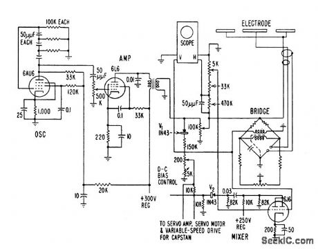
Uses sensing probe as one arm of capacitance bridge that is normally balanced with respect to 10-kc phase-shift oscillator signal. Oscillator output is compared with bridge unbalance in mixer that determines directional error. Output of mixer is amplified to control servo-driven rheostat which in turn controls speed at which wire is pulled, to hold capacitance within desired limits. Sensing electrode is water trough, with water in contact with extruded insulation to form one side of unknown capacitor. Wire is grounded to form other side.-J. Markus and V. Zeluff, Handbook of Industrial Electronic Control Circuits, McGraw-Hill, N.Y., 1956, p 18. (View)
View full Circuit Diagram | Comments | Reading(795)
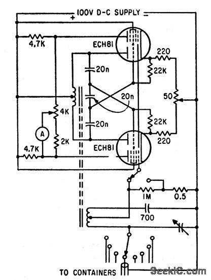
BALANCED_CAPACITANCE_FENCE_ALARM
Published:2009/7/16 5:53:00 Author:Jessie
Sets off alarm when anyone approaches barbed wire fence around power plant or substation. Automatically corrects for capacitance changes due to weed growth and changing weather conditions. Two separate antennas and two oscillators are used, with lines along fence serving as part of tuning capacitance of each oscillator. Mixer produces beats between harmonics. Frequency-selective network in low a-f range produces d-c voltages that trigger relay tubes and actuate alarm relays. – J. Markus, Handbook of Electronic Control Circuits, McGraw-Hill, N.Y., 1959, p 1. (View)
View full Circuit Diagram | Comments | Reading(1904)
PROXIMITY_SWITCH
Published:2009/7/16 5:50:00 Author:Jessie
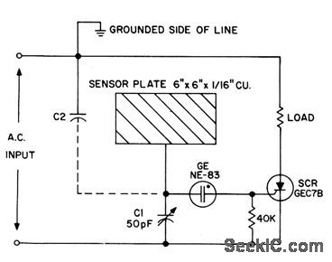
Sensor plate and C2 form capacitive voltage divider across a-c supply. Value of C2 depends on proximity to sensor plate of human body, grounded object, or other reasonably conductive object. When voltage across C1 exceeds breakdown of neon, C1 and C2 discharge through scr gate, causing scr to trigger and energize load. Latching action is obtained by driving scr an ode circuit with d-c, for such applications as elevator floor selector buttons and door safety controls.- Silicon Controlled Rectifier Manual, Third Edition, General Electric Co., 1964, p 122. (View)
View full Circuit Diagram | Comments | Reading(3528)
1_V_600_kHz_SWITCHING_SUPPLY
Published:2009/7/16 21:17:00 Author:Jessie
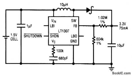
The LT1307 chip will produce 5 V at 40 mA or 3.3 V at 75 mA from a single AA-cell power source. It operates at 600 kHz and uses 60-μA standby current, and it has a low-battery detector. (View)
View full Circuit Diagram | Comments | Reading(622)
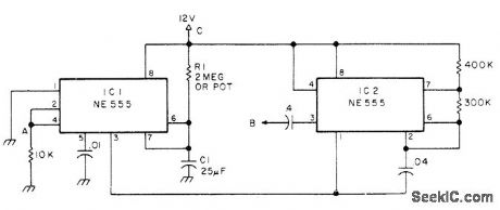
ON_OR_OFF_CONTROL
Published:2009/7/12 23:19:00 Author:May
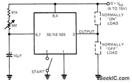
Circuit shows two ways of connecting 555 timer IC, for switching load on or switching load off at end of timing interval determined by setting of 5-megohm pot (1 to 60 s) and initiated by manual start switch. If desired, both loads can be connected to circuit for simultaneous switching.-E. R. Hnatek, Put the IC Timer to Work in a Myriad of Ways, EDNMagazine, March 5, 1973, p 54-58. (View)
View full Circuit Diagram | Comments | Reading(761)
POWER_SUPPLY_MONITOR
Published:2009/7/16 21:05:00 Author:Jessie
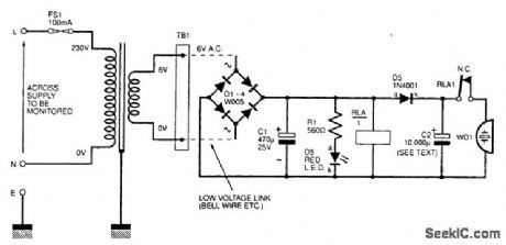
The power supply is monitored by T1, a low-voltage step-down transformer. A standard full-wave power supply is used on the secondary winding to illuminate LED D5, and also operate the relay RLA1 and charge a large-value electrolytic capacitor (C2). The relay has normally closed (NC) contacts, which remain open while mains power is present through transformer T1, allowing the output from the bridge rectifier to power the relay coil. Power failure causes the relay to drop out and the normally closed contacts will now connect the piezo buzzer across capacitor C2. The stored voltage across C2 is enough to sound the buzzer for several minutes. The relay contacts could alter-natively be used to drive an isolated circuit, such as a buzzer and battery. The circuit might also appeal to tropical fish keepers or possibly deep-freeze owners. (View)
View full Circuit Diagram | Comments | Reading(0)
HORIZONTAL_DRIVE
Published:2009/7/16 21:02:00 Author:Jessie
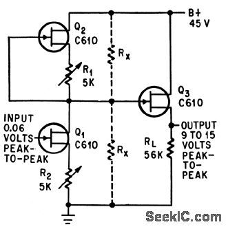
Three field-effect transistors give 45 db voltage gain for 1-cps riangular wave in horizontal defection circuit of crt.-F. J. Murphree and J. H. Hammond Jr., High-gain D.C Amplifier Drives CRT Display, Electronics, 37:19, p 53. (View)
View full Circuit Diagram | Comments | Reading(1177)
SIMPLE_25_MHz_COUNTER
Published:2009/7/12 22:56:00 Author:May
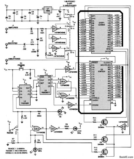
An Intersil ICM7224 is used to drive an LCD003 four-digit LCD display unit. Three inputs are provided, which add signal conditioning, either gain, rectification, or unbuffered input. A Statek PXO-1000 1-MHz clock is used as a frequency reference. S2 selects gate time and hence range, with LED1, LED2, and LED3, indicating Hz, kHz, or MHz, respectively. (View)
View full Circuit Diagram | Comments | Reading(2332)
BEAM_INTENSITY_CONTROL
Published:2009/7/16 20:59:00 Author:Jessie
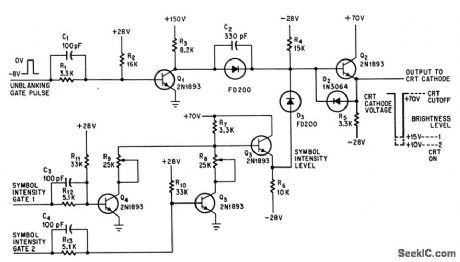
Used to provide two different intensities for symbols on crt.-A. E. Popodi, Reliable Repertoire Of Display Circuits, Electronics, 38:2, p 60-66. (View)
View full Circuit Diagram | Comments | Reading(692)
STEP_UP_SWITCHINC_IC_INVERTER
Published:2009/7/16 20:56:00 Author:Jessie
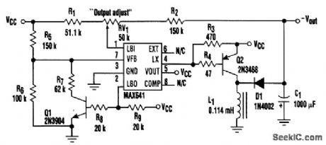
A popular step-up switching IC can be made to supply a negative voltage. The MAX641BCPA is a boost converter intended for use with 3-V batteries. To get the 641 to function as an inverter, some of its pin functions must be altered. Pin 1 is used as the voltage-feedback input, and pin 2 is used as the overvoltage-detector output. When the voltage on pin 1 falls below + 1.31 V, pin 2 becomes a low-impedance path to ground. This will force Q1 to cut off and allow the voltage on pin 7 to rise. When the voltage on pin 7 exceeds +1.31 V, the internal oscillator shuts off. At this point, the output voltage is equal to or less than the set level. When C1 discharges to a point where the voltage on pin 1 rises above +1.31 V, pin 2 will change to a high impedance, allowing Q1 to saturate and pull pin 7 below +1.31 V. This causes the internal oscillator to turn on. Pin 4, the output of the internal oscillator, will pump C1 negative while the oscillator is running. For the values shown in the figure, the adjustable output voltage range is approximately -4 to -13 V. The magnitude of the drivable load depends on how much ripple can be tolerated. The values shown will easily drive a 50- to-75-mA load and provide good regulation. (View)
View full Circuit Diagram | Comments | Reading(914)
90_s_TALKING_LIMIT_WARNING
Published:2009/7/12 22:55:00 Author:May
Developed for AM radio transceivers making use of repeaters, to limit length of individual transmission so as to avoid being timed out at repeater. Uses NE-555 connected as timer, with C1 and R1 chosen to set timing at about 90 s. Point A is connected to terminal of TB switch that goes from neutral or ground on receive to 12 V on transmit. Timing cycle begins on transmit; when IC1 times out, it activates IC2 connected as 1000-Hz astable oscillator driving transceiver connected to B. Tone sounds until microphone button is released to reset timer.-S. Kraman, Try the Mini-Timer, 73 Magazine, June 1977, p 48. (View)
View full Circuit Diagram | Comments | Reading(795)
TALK_TlMER
Published:2009/7/12 22:54:00 Author:May
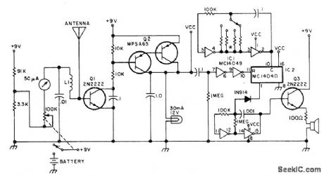
Switch gives choice of intervals from 0.5 to 5 min after going on air, before timeout alarm tone sounds. Circuit includes field-strength meter and on-the-air Iight. Releasing mike button for about 1 s resets timer, which consists of MC14049 hex inverter and MC14040 12-bit ripple counter. L1 is 3 tums No. 20 wire on 5/16-in form. Timing resistor values are 47Kfor 0.5 min, 100K for 1, 220K for 2, 390K for 3, and 510K for 5 min.-B. Fette, An FM Gadget, 73 Magazine, April1977, p 154-155. (View)
View full Circuit Diagram | Comments | Reading(2869)
AUTOMATIC_VOLTAGE_CONTROLLER
Published:2009/7/12 22:51:00 Author:May
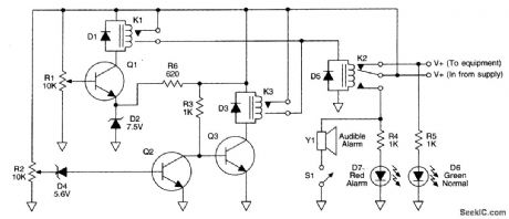
Station dc voltage, a nominal 113.8 Vdc, is fed through the normally closed contacts of relay K2. This voltage also provides power for the protective circuit illustrated. The voltage appears across R1 and R2, 10-kΩ trimpots, the wipers of which are set to exactly midrange, measuring a nominal 16.9 V dc. As the station dc varies between 111.2 and 115 V, the voltage at the wipers will vary from 5.6 to 7.5 Vdc. Zener diode D2 controls the high-voltage limit of 115 Vdc. R5 and zener diode D4 control the low-volt-age limit of 111.2 Vdc. Avoltage is fed from the wiper of R1 directly to the base of Q1, relay K1 is not energized, and its normally open contacts prevent relay K2 from being energized, allowing station dc to flow through K2's normally closed contacts. Above 115 V, the voltage at the base of Q1 also rises to or above 17.5 V, energizing K1, whose normally open contacts close, energizing K2, whose normally closed contacts open, removing the voltage from the station equipment. Should the voltage fall to or below 111.2 Vdc, zener diode D4 ceases to conduct, cutting off Q2, which causes Q3 to conduct, energizing K3. K3 applies operation voltage through its contacts to the coil of relay K2, opening its normally closed contacts, removing voltage from D6, the station equipment, and applying power to LED D7 and the audible alert.
(View)
View full Circuit Diagram | Comments | Reading(997)
RAIN_ALARM
Published:2009/7/12 22:45:00 Author:May
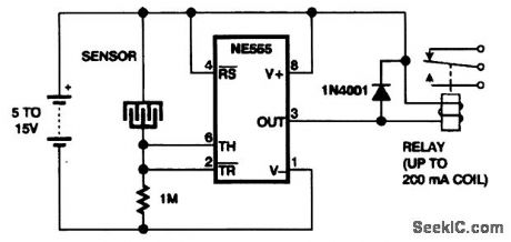
This rain-detector circuit closes the relay when water bridges the gap between the metal elecLrodes. (View)
View full Circuit Diagram | Comments | Reading(0)
TAMPER_ALARM
Published:2009/7/12 22:44:00 Author:May
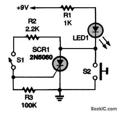
The silicon-controlled rectifier (SCR1) operates as a memory device to indicate a security breach in a room, desk drawer. safe. etc. Switch S1 can be a mechanical or magnetic switch. Position S1 in an object that you want to keep protected, making sure that the switch will close when the object is tampered with. When S1 closes, SCR1 turns on, lighting LED1. Pressing S2 resets the circuit. (View)
View full Circuit Diagram | Comments | Reading(1126)
| Pages:107/312 At 20101102103104105106107108109110111112113114115116117118119120Under 20 |
Circuit Categories
power supply circuit
Amplifier Circuit
Basic Circuit
LED and Light Circuit
Sensor Circuit
Signal Processing
Electrical Equipment Circuit
Control Circuit
Remote Control Circuit
A/D-D/A Converter Circuit
Audio Circuit
Measuring and Test Circuit
Communication Circuit
Computer-Related Circuit
555 Circuit
Automotive Circuit
Repairing Circuit