
Control Circuit
Index 111
TIME_ON_TOUCH_SWITCH
Published:2009/7/11 1:23:00 Author:May
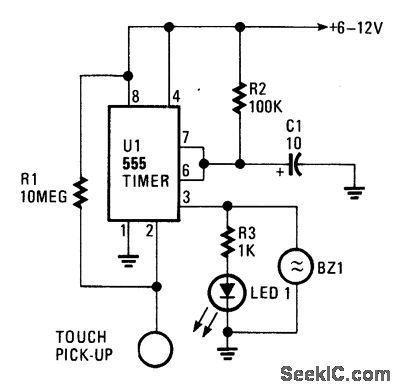
The circuit is built around a 555 oscillator (U1), which is tumed on when a trigger is applied by touching the touch terminal to pin 2 of U1. When activated, LED1 and BZ1 (a piezoelectric buzzer) tum on for the time period set by the values of R2 and C1. The ON-time of the touch circuit can be altered by changing the values of Q and R2.This touch switch can be powered from batter-ies so that it need not be near a 60-Hz power source for triggering. The extremely small amount of current supplied to the trigger input through the 10-MΩ resistor. R1, makes the input circuitry very sensitive to any external loading, and it is easily triggered by touching the pickup. (View)
View full Circuit Diagram | Comments | Reading(916)
TOUCH_SWITCH_Ⅱ
Published:2009/7/11 1:21:00 Author:May
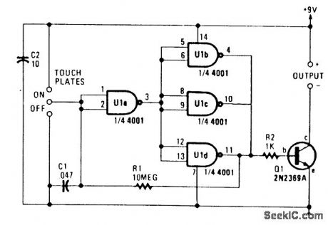
U1A and U1B/U1C/U1D form a bistable multivibrator that drives Q1, which switches the load. Touching the two upper contacts makes Q1 conduct; the two lower contacts cause Q1 to cut off. (View)
View full Circuit Diagram | Comments | Reading(718)
ON_OFF_TOUCH_SWITCH
Published:2009/7/11 1:20:00 Author:May
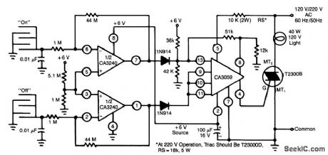
This circuit uses a CA3240 dual BiMOS op amp to sense small currents flowing between the contact points on a touch plate. The high input impedance of the CA3240 allows the use of 1-MΩ resistors in series with the touch plates to ensure user safety. A positive output on either pin 7 (ON) or pin 1 (OFF) of the CA3240 actuates the CA3059 zero-voltage switch, which then latches the triac on or turns it off. The internal power supply of the CA3059 powers the CA3240. (View)
View full Circuit Diagram | Comments | Reading(0)
TOUCH_SWITCH_Ⅰ
Published:2009/7/11 1:18:00 Author:May
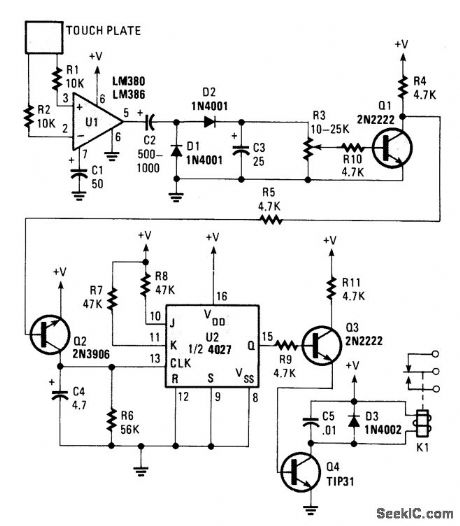
This switch reacts to the touch of a finger to turn lights and/or appliances on or off. The device uses the human body as an antenna to pick up 60-Hz hum, which is applied to a metal plate by your finger. The signal is fed to the input of U1, an LM380 audio-power amplifier. An LM386 should work as well.The 60-Hz output from the amplifier is rectified by D1 and D2, then filtered by C3. Potentiometer R3 sets the trigger voltage used to saturate Q1. When Q1 turns on, the collector end of R4 goes almost to ground and provides the needed voltage to turn on Q2. Transistor Q2 turns on and clocks. The flip-flop is configured for toggle-mode operation, so its output switches states with each clock pulse.The 4027 (U2) is wired to toggle by tying the J and K inputs high and the set and resets low. Transis-tor Q3 is connected to the Ooutput through the 4.7-kΩ resistor. Transistor Q3 drives Q4, the relay driver. Be sure that the load does not exceed the relay ratings. (View)
View full Circuit Diagram | Comments | Reading(1071)
5_MC_CRYSIAL_FREQUENCY_CONTROL
Published:2009/7/11 1:16:00 Author:May
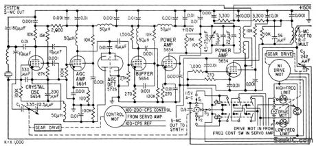
C1 provides fine frequency control of 5-Mc primary frequency standard, when driven by 100-cps control signctl from cesium beam tube.This will change frequency up to 2.5 cps,sufficient for short-lime drifts over several days. When C1 reaches either end of its range, cam doses s1 or s2 and energizes drive motor M1 for C2. Lorge capacitor is then driven in direction that will make small capacitor return to middle of its range.-W.A. Mainberger, Primary Frequency Standard Using Resonant Cesium, Electronics, 31:45, p80-85. (View)
View full Circuit Diagram | Comments | Reading(650)
ACTIVE_TONE_CONTROL
Published:2009/7/11 1:13:00 Author:May
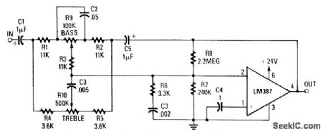
The use of a low noise LM387 in a feedback circuit provides 20-dB boost or rejection of treble and bass. The supply voltage is +24 V. (View)
View full Circuit Diagram | Comments | Reading(2075)
ROBOTIC_MOTOR_CONTROL_CIRCUIT
Published:2009/7/17 4:11:00 Author:Jessie
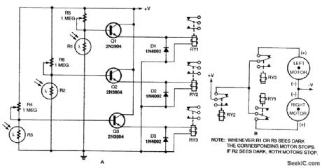
This circuit, with three light sensors and three relays, was used to allow a robot to follow a light beam. Loss of the beam causes relay actuation, which controls a motor that produces corrective action. (View)
View full Circuit Diagram | Comments | Reading(806)
WATCHDOG_TIMER_ALARM
Published:2009/7/11 0:59:00 Author:May
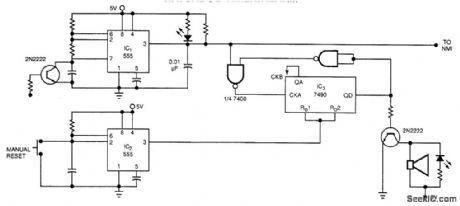

The watchdog timer contains a counter, IC3, in addition to the usual retriggerable 555 timer, IC1. The counter will sound an audible alarm if the watchdog timer trys to reset the μP a certain number of times (8, in the case of the counter). The alarm indicates that despite numerous resets, the system μP has failed to restart successfully, and the system is truly dead.A second 555 timer, IC2, resets the counter, 1C3, for the duration of the manual system restart. The design could be modified so that system μP resets the counter. (View)
View full Circuit Diagram | Comments | Reading(1705)
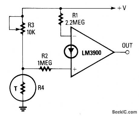
OVER_TEMPERATURE_SWITCH
Published:2009/7/11 0:32:00 Author:May

The output goes high when a preset tempera-ture is exceeded. A fixed half-supply reference voltage feeds a reference current to the inverting input, and a variable current is fed to the noninvert-ing input. Resistor R6 is a negative-temperature-coefficient (NTC) thermistor, so the potential at the junction of R5 and R6 rises with temperature. The op amp will switch high when that voltage exceeds the half-supply value. The trip temperature can be preset via R5. (View)
View full Circuit Diagram | Comments | Reading(1020)
WATER_LEVEL_MONITOR
Published:2009/7/17 4:06:00 Author:Jessie
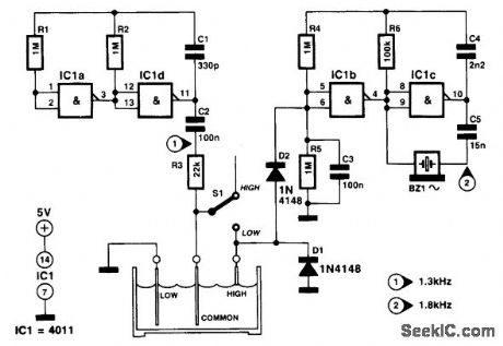
This circuit was devised to produce art audible alarm when a water tank was approaching empty. The circuit consists of two conventional CMOS oscillator gate pairs, as found in the textbooks. With the switch in the LOW position, gates IC1a and IC1d provide an alternating current flow through C2, R3, the common electrode, the water, and the low electrode, to earth. When the water level drops, the circuit to earth is interrupted, and the ac then fed via S1 to the junction of D1 and D2. This charges C3 so that pin 5 of IC1b goes positive, causing gates IC1b and IC1c to start oscillating. The audible transducer is an ac buzzer. The switch is then moved to the HIGH position. Pin 6 of IC1 is then at ground potential via R5, waiting for the tank to fill and connect the common and high electrodes via the water. The ac then flows through D2 to once again sound the alarm. The pump is turned off and S1 is restored to sense empty once more. The rate of charge of capacitor C3 can be changed by altering the value of R3. The power supply for the circuit can be from 5 to 12 V. (View)
View full Circuit Diagram | Comments | Reading(1181)
UNDER_TEMPERATURE_SWITCH
Published:2009/7/11 0:30:00 Author:May
The reference current is fed from the supply voltage via R1, to the inverting terminal, and the variable (noninverting) current is supplied from the junction of R3 and R4. Because the value ofR1 is approximately double that of R2, and generates a current that is proportional to the supply voltage, the trip temperature (preset via R3) is independent of the supply voltage. (View)
View full Circuit Diagram | Comments | Reading(892)
TEMPERATURE_CONTROLLER
Published:2009/7/11 0:21:00 Author:May
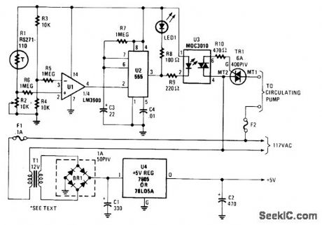
A thermistor (R1) is compared with a reference (R2) in a Wheatstone-bridge circuit. Comparator U1's output goes high, which triggers U2. U2 is a delay of about 25 s. After 15 s, LED1 lights, U3 actuates, triac TR1 triggers, and turns on a hot water pump. This system was used with a hot-water heater. (View)
View full Circuit Diagram | Comments | Reading(0)
THERMOCOUPLE_TEMPERATURE_CONTROL
Published:2009/7/11 0:16:00 Author:May
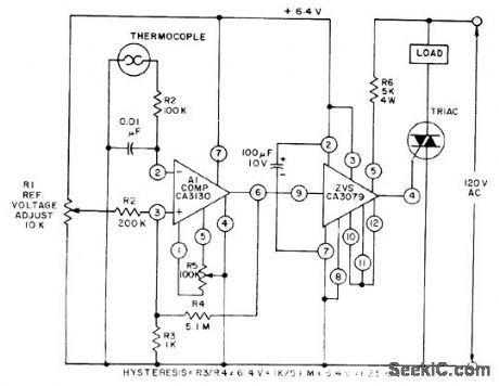
This control, with zero-voltage load switching, uses a CA3130 BiMOS op amp and a CA3079 zerovoltage switch. The CA3130, used as a comparator, is ideal because it can compare the low voltages generated by the thermocouple to the adjustable reference voltage over the range or0 to 20 mV. (View)
View full Circuit Diagram | Comments | Reading(0)
TGS_gas_smoke_detector_with_triac_control
Published:2009/7/17 3:56:00 Author:Jessie
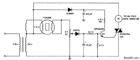
TGS gas/smoke detector with triac control(courtesy Motorola Semiconductor Products Inc.). (View)
View full Circuit Diagram | Comments | Reading(858)
MODEL_TRAIN_CROSSING_FLASHER_WITH_SENSOR_SWITCH
Published:2009/7/17 3:41:00 Author:Jessie
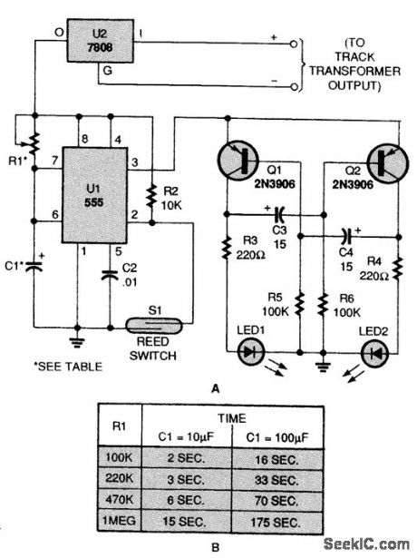
Featuring a reed switch operated by train proximity, this circuit (A) has everything you need to activate an LED-based crossing signal. To change the time period of U1, use these substitutions (B). (View)
View full Circuit Diagram | Comments | Reading(1160)
CLOCK_WITH_REFRESH_CONTROLS
Published:2009/7/10 22:54:00 Author:May

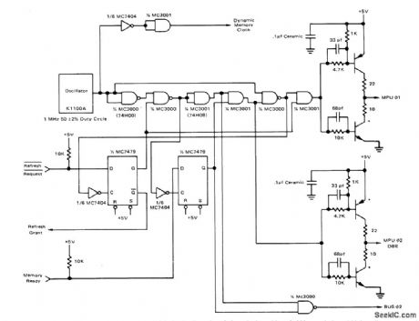

Crystal-stabilized 1-MHz clock source such as Motorola K1100A produces complementary 5-V clock outputs required for phases 1 and 2 of MC6800 MPU and also provides interface signals required for dynamic (refresh request and refresh grant) and slow (memory ready) memories. Refresh control circuit uses MC7479 dual latch, MC7404 hex inverter, and pair of 10K pull-up resistors. If ref resh request state is low when sam pled during leading edge of phase 1, phase 1 is held high and phase 2 low for at least one full clock cycle. Refresh grant signal is high to indicate to dynamic memory system that refresh cycle exists. If memotry ready line is low when sampled on leading edge of phase 2, phase 1 is held low and phase 2 high until memory ready line is brought high by slow memory controller.All transistors are MP06842.- Microprocessor Applications Manual (Motorola Series in SolidState Electronics), McGraw-Hill, New York, NY, 1975, p 4-57-4-58. (View)
View full Circuit Diagram | Comments | Reading(861)
SIGNAL_SWITCHER
Published:2009/7/10 22:40:00 Author:May
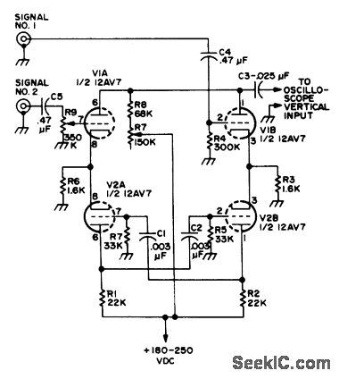
Two-tube electronic switch serves in effect to provide simultaneous presentation of two different signals on CRO screen by switching signals alternately to vertical input at rate fast enough so both displays are seen.-Novice Q & A, 73 Magazine, March 1977, p 187. (View)
View full Circuit Diagram | Comments | Reading(733)
SCANNING_KEYBOARD_ENCODER
Published:2009/7/10 22:30:00 Author:May
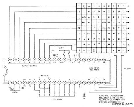
Uses RCA CA3600 IC for sampling 90 keys and providing parallel ASCII output with parity. Network on pins 1-3 sets clock at 50 kHz. Capacitor on pin 31 sets debouncetime at about 8 ms. Uppercase only or both uppercase and lowercase can be selected by switching between pins 7 and 9.Provides two-key rollover; N-key rollover can be obtained by adding diodes to keys. Each output will drive one TTL load.-D. Lancaster, TV Typewriter Cookbook, Howard W. Sams, Indianapolis, IN, 1976, p 38. (View)
View full Circuit Diagram | Comments | Reading(2197)
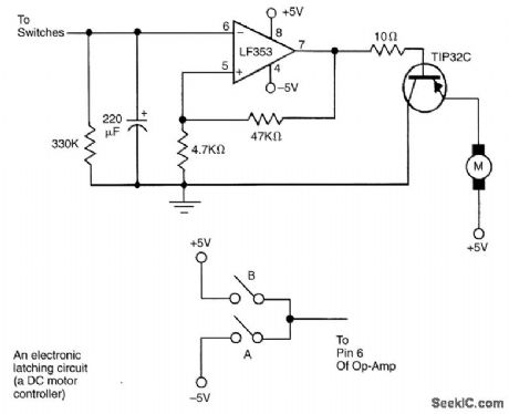
ELECTRONIC_LATCH_DC_MOTOR_CONTROLLER_CIRCUIT
Published:2009/7/17 4:12:00 Author:Jessie
View full Circuit Diagram | Comments | Reading(2037)
UNIVERSAL_REMOTE_CONTROLLED_ROBOT
Published:2009/7/17 4:13:00 Author:Jessie
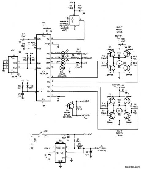
This project uses a microcontroller programmed with software that is posted on the Gerns-back BBS at 516-293-2283 as part of RUNABOUT.ZIP. The robot can be controlled via a universal remote control. (View)
View full Circuit Diagram | Comments | Reading(1725)
| Pages:111/312 At 20101102103104105106107108109110111112113114115116117118119120Under 20 |
Circuit Categories
power supply circuit
Amplifier Circuit
Basic Circuit
LED and Light Circuit
Sensor Circuit
Signal Processing
Electrical Equipment Circuit
Control Circuit
Remote Control Circuit
A/D-D/A Converter Circuit
Audio Circuit
Measuring and Test Circuit
Communication Circuit
Computer-Related Circuit
555 Circuit
Automotive Circuit
Repairing Circuit