
Control Circuit
Index 119
DIAC_TRIAC_PHASE_CONTROL_OF_5_AMP_LOAD
Published:2009/7/20 6:19:00 Author:Jessie
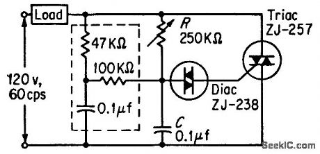
Uses two types of semiconductor switches together with R and C to give continuous control of power. Addition of second phase shift network (enclosed in dashed box) extends range of control to cover 5 to 95% of full power.-M. P. Southworth, Bidirectional Static Switch Simplifies Ac Control, Control Engineering, March 1964, p 75-76. (View)
View full Circuit Diagram | Comments | Reading(991)
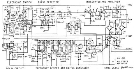
HOLD_SAMPLE_HOLD_PHASE_DETECTOR
Published:2009/7/20 5:53:00 Author:Jessie
Has two mos transistors as series switches and a third as impedance transformer. C5, C6, and C8 are charged to voltages proportional to phase difference between programmed dilvider's output and reference signal. Voltages are summed with pretuning voltage to control vco of frequency synthesizer for military uhf transceiver.-L. F. Blachowicz, Dial any Channel to 500 Mhz, Electronics, 39:9, p 60-69. (View)
View full Circuit Diagram | Comments | Reading(997)
LAMP_DIMMER
Published:2009/7/20 5:50:00 Author:Jessie
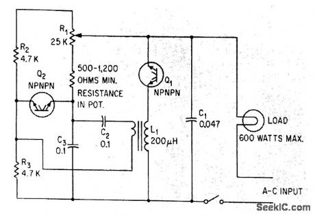
Silicon symmetrical switches Q1 and Q2 control phase angle at which current flows fhrough 600-w fluorescent or incandescent lamp load. Q1 handles load current while Q2 serves as symmetrical relaxation oscillator, with setting of R1 determining point in each half-cycle at which Q2 fires. Since system is symmetrical, it cannot be damaged by transients or line surges.-S. B. Gray, Home and Auto Controls, Electronics, 36:19, p 52-56. (View)
View full Circuit Diagram | Comments | Reading(0)
MEASURING_PHASE_UP_TO_2000_MC
Published:2009/7/20 5:47:00 Author:Jessie
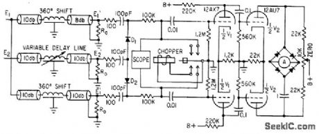
Output is fed to cro having 100-kc bandwidth. In operation, time delay of both channels is equalized by applying identical signal to both inputs, then reference and unknown signals are applied to input terminals and variable delay line is adjusted again for null on chopper amplifier that drives d-c milliammeter.-Y. P. Yu, How to Measure Phase at High Frequencies, Electronics, 34:11, p 54-56. (View)
View full Circuit Diagram | Comments | Reading(682)
PULSE_CHAIN_PHASEMETER
Published:2009/7/20 5:18:00 Author:Jessie
Measures phase difference as small as 0.005 deg between pulses of two nearly coincident pulse chains using electronic switch, mvbr phase detector, and diode synchronous detector. Output shows both sign and magnitude of phase angle between two corresponding pulses in pulse chains.-F. Vrataric, Jr., Electronic Switching in Phase Measurement, Electronics, 32:23, p 60-61. (View)
View full Circuit Diagram | Comments | Reading(2231)
1_KW_A_C_PHASE_CONTROL
Published:2009/7/20 5:09:00 Author:Jessie
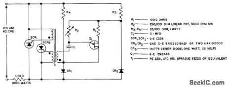
Inverse-parallel circuit is economical for manual control of lights, heaters, ovens, or fans.- Silicon Controlled Rectifier Manual, Third Edition, General Electric Co., 1964, p 138. (View)
View full Circuit Diagram | Comments | Reading(606)
BACK_UP_ALARM
Published:2009/7/9 4:40:00 Author:May
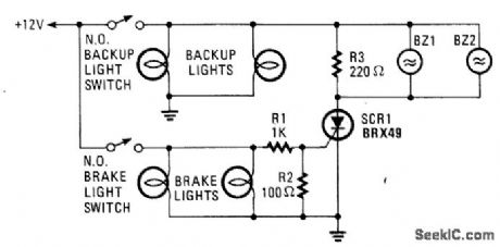
The brake lights of the automobile trigger this circuit on and off. This saves the annoyance of the alarm when it is not needed. (View)
View full Circuit Diagram | Comments | Reading(1211)
LOW_CURRENT_SIMPLE_CMOS_ALARM
Published:2009/7/9 4:39:00 Author:May
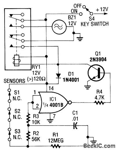
This CMOS-aided alarm draws only 1μA standby current. An open sensor allows IC1 to bias Q1 on, activating RY1. (View)
View full Circuit Diagram | Comments | Reading(640)
SINGLE_IC_ALARM
Published:2009/7/9 4:36:00 Author:May
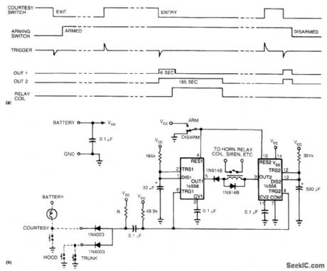
With a single IC, you can build a simple, reliable auto burglar alarm or a similar alarm. See (a) for the timing information for the alarm circuit in (b).
When you leave your vehicle, flip the arming switch and close the door,behind you to arm the device.Subsequent opening of an entrance triggers both timers. After the expiration of the entry delay timer, the alarm sounds for a time that is determined by the second timer.
The value of R should be less than 1 kΩ. If you use an incandescent lamp instead of a resistor, you get an extra function-an open-entrance indicator. By keeping the resistance low, you avoid false tripping should water collect under the hood.
If your door switch connects the courtesy light to 12 V rather than to ground, use a single transistor as an inverter at the input. Although this circuit's simplicity has its drawbacks, you can add more features, such as no-entry delays for the hood and trunk, and retripping when doors remain open. (View)
View full Circuit Diagram | Comments | Reading(836)
AUTOMATIC_TURN_OFF_ALARM_WITH_DELAY
Published:2009/7/9 4:34:00 Author:May
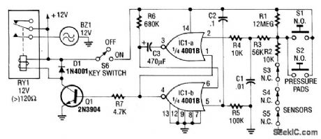
In this circuit, IC1A and IC1B act as a monostable multivibrator. Any input from the sensors S1 through S5 forces IC1A to produce logic low, which causes IC1B to turn on Q1 until C3 changes through R6. This action resets the latch formed by IC1A and IC1B. (View)
View full Circuit Diagram | Comments | Reading(783)
REACTION_TIMER
Published:2009/7/9 4:33:00 Author:May

This circuit uses a timer to generate at a 5-ms clock rate.The pulses are shifted into the shift register,one at a time,lighting an LED.An auxiliary timer that generates one pulse per second is used to generate timing to activate the go LED and stare the 5ms pulses clocking into the registers.At the GO signal each player presses his buttons (S3 or S4).The delay (reaction time) is read out on LED4 to LED17;after six seconds,the sequence repeats. (View)
View full Circuit Diagram | Comments | Reading(1485)
CASCADED_TWO_TUBE_PHASE_SHIFTER
Published:2009/7/20 6:23:00 Author:Jessie
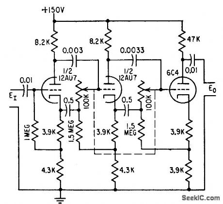
Provides phase shifts well over 180°with highly constant output voltage. Use of tubes in place of transformer gives wide-band operation, from 500 to 2,000 cps.-W. G. Shepard, Phase Shifter Range Exceeds 180°, Electronics, 31:19, p 96-100. (View)
View full Circuit Diagram | Comments | Reading(1644)
AUTO_IGNITION_CUT_OFF
Published:2009/7/9 4:30:00 Author:May
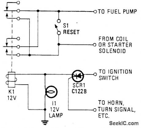
Using an SCR/relay combination, this circuit can be made to cut off ignition, unless a positive voltage is applied to'the gate of the SCR. This is useful as an anti-theft device, because depending on hook-up, the 'car wili not start unless a certain accessory or a hidden switch is closed. (View)
View full Circuit Diagram | Comments | Reading(1291)
AUTO_ALARM
Published:2009/7/9 4:29:00 Author:May
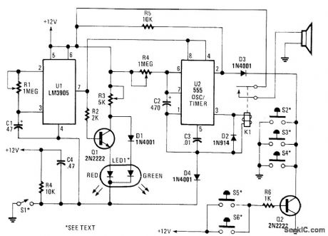
S1 is external key switch. The alarm allows a 0-to 45-s delay after S1 is operated before the circuit is armed. During this period, LED1 lights green. After this delay, LED1 lights red, which indicates that the circuit is armed. Then, sensors S2 through S4 -(NO) or S5 through S6 (NO) pull pin 2 of U2 low, which activates K1 and sounds the alarm. The alarm sounds for a duration determined by R4 and C2. After this time, K1 releases and the circuit is again ready. Manual reset is via the key switch, S1. (View)
View full Circuit Diagram | Comments | Reading(1814)
PHASE_SHIFTING_ANTENNAFIER
Published:2009/7/20 6:59:00 Author:Jessie
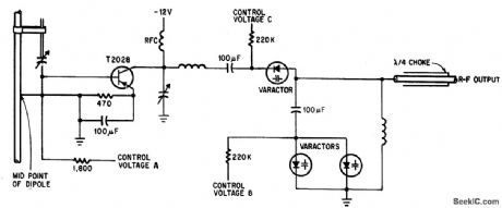
Control voltages A,B, and C together produce up to 180°phase shift with adequate matching, for beam-steering arrays. Ganged potentiometers with appropriately tapered windings can provide the control voltages and relate beam position to shaft rotation.-J. F. Rippin, Making the Antenna an Active Partner, Electronics, 38:16, p 93-96. (View)
View full Circuit Diagram | Comments | Reading(673)
PHASE_INDICATOR
Published:2009/7/20 6:56:00 Author:Jessie

Used to determine succession of phases of three phase 120-V a-c source used in synchro work. Terminals A, B, and C are connected to terminals of source to be checked. If neon lamp comes on, interchange any two leads; light then goes out, and A, B, and C then indicate correct sequence. Also serves as phase failure monitor, because neon lamp will come on if power on any one line is lost.-G. Richwell, Phase Indicator, EEE, 12:11, p 70. (View)
View full Circuit Diagram | Comments | Reading(0)
AUTOMATIC_ARMING_AUTO_ALARM
Published:2009/7/9 4:20:00 Author:May
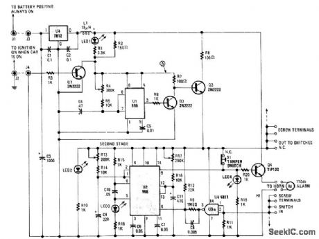
The circuit automatically turns on when the car is turned off. It gives you a variable time to get out and lock up, and also provides a variable time delay to get in and start the car.
The 555 oscillator/timers are always powered down when the car is on. That keeps the alarm from going off while you're driving. As soon as the car is turned off, Q2 switches off and shunts power to U1. When that happens, U1 immediately sends its output high, keeping Q3 on, and thereby prevents power from returning to U2.
Transistor Q2 also sends power to Q3's collector to be used only when U1 has completed its timing cycle. When U1 has finished, it turns Q3 off, which in turn activates Q4, and sends power to the balance of the circuit. That timing period was the time needed to get out of the car. LED1 indicates that the system is disarmed and LED2 indicates that the system is armed.
At this point, U2 whits for a trigger pulse from the car's door switches or dome light. A positive impulse at the 4011's input sends a negative trigger pulse to the first stages of U2, which is connected as a cascading timer. The first stage's output becomes high for a time to allow the car to be turned on.
If that does not happen, the first stage's output lowers, which sends a low trigger pulse to the second stage. The second stage then sends its output high, turning on Q5, which sounds the alarm for a given time. Once that time has elapsed, the alarm is shut off by a low output to Q5 and the system is reset. If the car door is closed or a second door opened while the alarm is sounding, the first stage retriggers and pre-pares to extend the ON-time of the alarm.
The cascading or counting action continues until the car is left alone. You can add a switch on the positive supply rail at J3 to override and silence the alarm, if (for example) you plan to work on the car.Switch S1 is a normally closed type that is built into the case of the alarm; S1 is pushed to the open posi-tion when the case is mounted flush with a surface. Any attempt to remove the alarm will sound the alarm. (View)
View full Circuit Diagram | Comments | Reading(892)
VARIABLE_0_180_DEG_PHASE_SHIFTER
Published:2009/7/20 6:54:00 Author:Jessie
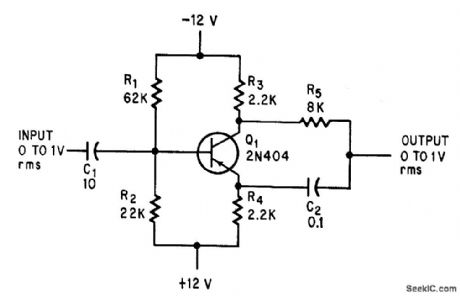
Single low-cost pnp germanium transistor circuit gives any desired phase between 0 and 180 degrees, at constant amplitude, for frequencies up to 3 Mc, by varying values of C2 and R5. Values shown gives 90° shift for 200 cps. –J. J. Collins, Single Transistor Provides Low-Cost Phase Shifter, Electronics, 37:16, p 92. (View)
View full Circuit Diagram | Comments | Reading(2634)
DIGITAL_MISCELLANEOUS_TEMPERATURE_GAUGE
Published:2009/7/9 4:15:00 Author:May
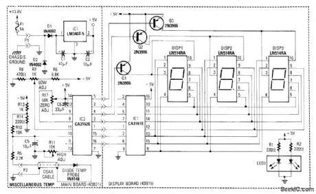
A diode (IN4148) is used as a temperature sensor. IC2 is an A/D converter with BCD output. A reference voltage set by R7 is applied to the positive input of IC2. As the temperature increases, the voltage across the temperature sensor resistance decreases. This increases the differential input voltage across pins 10 and 11 of IC2. R3 adjusts low calibration. R17 zeros the A/D converter and R7 adjusts high calibration. (View)
View full Circuit Diagram | Comments | Reading(1811)
PHASE_DIFFERENCE_METER_FOR_02_TO_20_KC_
Published:2009/7/20 6:34:00 Author:Jessie
Measures phase difference between two sinusoidal inputs. Each limiter (Q1 and Q2) drives one side of high-speed flip-flop Q3-Q4 through differentiating and clipping circuits, giving square wave that turns on when one input signal goes negative and turns off when other input goes negative. D-c value of output voltage is proportional to phase difference, with about 11 V corresponding to 360°.-J. R. Woodbury, Measuring Phase with Transistor Flip-Flops, Electronics, 34:38, p 56. (View)
View full Circuit Diagram | Comments | Reading(737)
| Pages:119/312 At 20101102103104105106107108109110111112113114115116117118119120Under 20 |
Circuit Categories
power supply circuit
Amplifier Circuit
Basic Circuit
LED and Light Circuit
Sensor Circuit
Signal Processing
Electrical Equipment Circuit
Control Circuit
Remote Control Circuit
A/D-D/A Converter Circuit
Audio Circuit
Measuring and Test Circuit
Communication Circuit
Computer-Related Circuit
555 Circuit
Automotive Circuit
Repairing Circuit