
Control Circuit
Index 104
BICOLOR_LED_SPST_SWITCH
Published:2009/7/13 4:43:00 Author:May
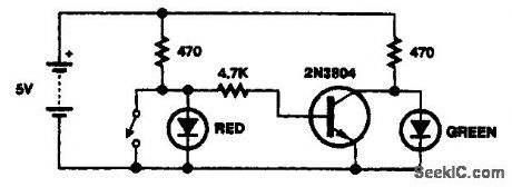
A transistor and a few resistors control two LEDs where the cathodes have a common lead. (View)
View full Circuit Diagram | Comments | Reading(1358)
TOUCH_SWITCH_2
Published:2009/7/13 4:31:00 Author:May
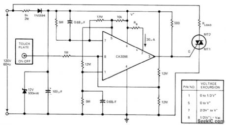
Small AC signal momentarily introduced by finger contact on touch plate causes voltage at pin 8 of CA3098 dual-input precision level detector to be greater than high reference voltage. This toggles memory flip flop in IC, making voltage high at pin 5. Vottage at pin 7 then increases exponentially to V+ in about 10 s.This 10-sdelay is maximumthat button can betouched; longertouch makes system oscillate between ON and OFF states until finger is removed. Shorter touch energizes load, placing pin 7 at V+. Next touch of plate turns circuit off.-G. J. Granieri, Precision Level Detector IC Simplifies Control Circuit Design, EDN Magazine, Oct. 5, 1975, p 69-72. (View)
View full Circuit Diagram | Comments | Reading(0)
CONTACTLESS_KEYBOARD
Published:2009/7/13 4:29:00 Author:May
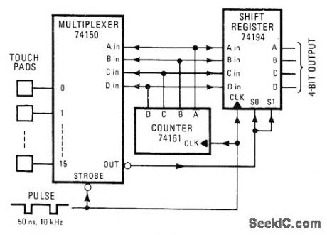
Touching one of 16 metal pads at inputs of 74150 multiplexor produces corresponding 4-bit BCD output from 74194 shift register. During scanning of multiplexer inputs by counter, output is produced only when finger of operator is on corresponding fingertip-size touch pad. Requires 10-kHz pulse from external source to strobe multiplexer and serve as clock for counter. Duration of clock pulse must be more than 20 ns so untouched pads charge up to threshold voltage but not long enough to let touched pad charge.-D. Cockerell, TTL IC Serves as Touch Keyboard, Electronics, Feb. 20, 1975, p 108-109. (View)
View full Circuit Diagram | Comments | Reading(3143)
LED Holiday Lights Controller
Published:2011/8/1 3:14:00 Author:Felicity | Keyword: LED, Holiday Lights, Controller
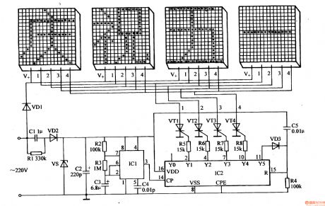
Work of the circuit
The circuit consists of Power supply circuit, pulse generator, the control circuit and LED display circuit. (It is showed in picture 1-165.)
Power supply circuit consists of buck capacitor Cl, discharge resistors Rl, rectifier diodes VDl, VD2, voltage regulator diode VS and filter capacitor C2.
Pulse generator consists of time-base integrated circuit ICl, resistors R2, R3 and capacitors C3, C4.
The control circuit consists of decimal counting / pulse distributor circuit IC2, diodes VD3, resistors R4-R8, capacitor C5 and thyristor VTl-VW.
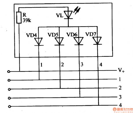
LED display circuit consists of four word light displays. Each display consists of 16x16 arrays of 256 word light units. Each word light unit consists of LED VL, current limiting resistor R and the isolation diode VD4-VD7. (It is showed in picture 1-166.)
(View)
View full Circuit Diagram | Comments | Reading(1748)
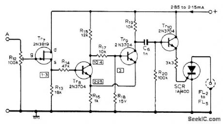
AUDIBLE_ALARM_FOR_TIMER
Published:2009/7/13 4:28:00 Author:May
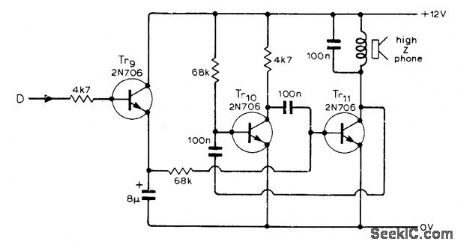
Used with 2-min timer for developing photographic paper, to produce short waming bleep indicating end of developing time. Input D is taken from output of Schmitt trigger that changes state when 2-min ramp generator times out. Tr9 and C4 to-gether lengthen short reset pulse so MVBR Tr10-Tr11 oscillates long enough for signal to be heard.-R. G. Wicker, Photographic Development Timer, Wireless World, April 1974,. p 87-90. (View)
View full Circuit Diagram | Comments | Reading(943)
FULL_WAVE_CONTROL_
Published:2009/7/13 4:23:00 Author:May
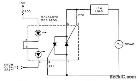
Monsanto MCS6200 dual SCR optocoupler provides direct full-wave control of 15-W lamp or other AC device when driven by output logic voltages of microprocessor. LEDs are connected in series and photo-SCRs in reverse parallel to create equivalent of triac.-H. Olson, Controlling the Real World, BYTE, March 1978, p 174-177.
(View)
View full Circuit Diagram | Comments | Reading(1158)
SENSITIVE_RELAY_CONTROL
Published:2009/7/13 4:20:00 Author:May
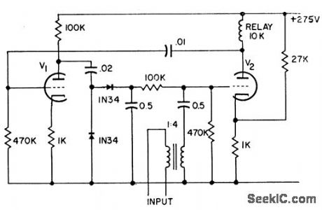
Reflex circuit ensures full use of available gain of two-stage relay control ampliler using 12AT7 twin-triode. Tube V2 controls relay in its plate circuit and also serves as a-c amplifier, increasing over-all sensitivity by factor approximately equal to a-c gain. Performs best about 400 cps.-Sensitive Relay Control Amplifier, Electronic Circuit Design Handbook, Mactier Pub. Corp.,N.Y.,p103. (View)
View full Circuit Diagram | Comments | Reading(785)
MULTIFLASH_SWITCH
Published:2009/7/13 4:20:00 Author:May
When ramp output of flash trigger circuit (given in article) is applied to input at A, flash at output of switch circuit is tripped when ramp voltage reaches level determined by setting of R12. Similar voltage-operated switches are required for other flashes.Used for taking sequence photographs such as springboard diver in flight. Settings of R12 for diferent switches are chosen for equal times between flashes, with intervals from 11 ms to 11 s. Article gives all circuits and set up procedure.Regulated 19.5-V supply is required-R. Lewis, Multi-Flash Trigger Unit, Wireless World, Nov.1973, p 529-532. (View)
View full Circuit Diagram | Comments | Reading(1038)
TOUCH_BUTTONS
Published:2009/7/13 4:16:00 Author:May
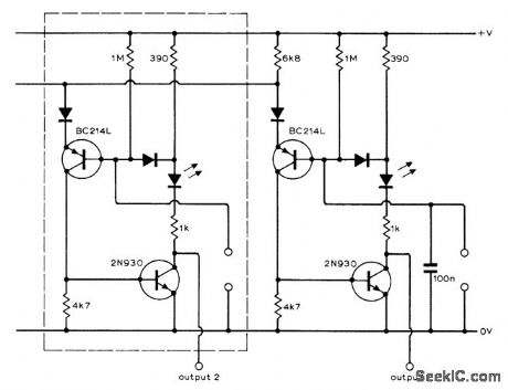
Based on detecting skin resistance between two contacts built into each touch button. Contact going to 0 V would normally be metal front panel of control. Any number of sections like that in dashed lines can be cascaded to handle more buttons. A particular button always comes on when power is applied, and is canceled by next button touched. LED identifies button currently activated; use any LED rated at 20 mA. Supply can be 20 to 30 V. Outputs may be used to drive FET analog switches, varactor tuning diodes, or relays.-P. G. Hinch, Self-Cancelling Touch Button Control, Wireless World, Oct. 1974, p 380. (View)
View full Circuit Diagram | Comments | Reading(1137)
CRT_GRAY_SCALE_CONTROL
Published:2009/7/13 4:13:00 Author:May
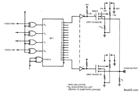
Circuit provides digital selection of up to 16 shades of gray for image on screen of cathode-ray tube, as required for different imaging requirements or different photographic films. DMOS FETs provide fast switching times so data rate is limited only by TTL drive circuits. Four bits of digital data stored in 9311 memory are used for selecting desired scale. Output of circuit is used to control beam intensity. Circuit also permits complete video inversion for negative.-K. R. Peterman, Fast CRT Intensity Selector Adjusts the Gray Scale, EDN Magazine, March 20, 1976, p 98 and 100. (View)
View full Circuit Diagram | Comments | Reading(784)
FLUORESCENT_LAMP_DIMMER
Published:2009/7/13 4:09:00 Author:May
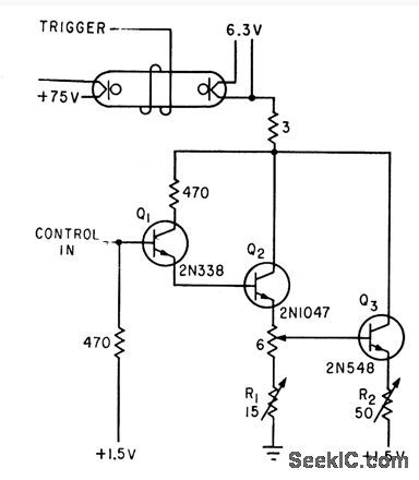
Tandem circuit with amplifier stages requires only 0.4 ma at 8V to drive 15-w fluorescent lamp at rated 300 ma while providing range of about 200 to 1 in luminance control. Conventional pho toflash trigger gives reliable starting for Lamp currents down to 1 ma.-L. L. Blackmer and A. T. Wright, Tandem-Transistor Circuit Regulates Fluorescent lamp,Electronics, 34:17, p114-116. (View)
View full Circuit Diagram | Comments | Reading(0)
VOLUME_UNIT_DISPLAY_AND_ALARM
Published:2009/7/13 4:09:00 Author:May
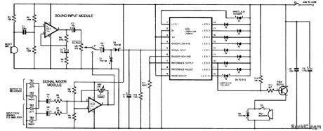
This circuit uses two audio amplifiers, one for a microphone and one for a stereo input, to drive an LED bar-graph display, rather than a meter. When the input exceeds a certain level, an LED (#8 in this circuit) will light and also cause an alarm buzzer or some other signal to actuate. A switch is provided for source selection. (View)
View full Circuit Diagram | Comments | Reading(1355)
GYRO_TORQUING_SWITCH
Published:2009/7/13 3:57:00 Author:May
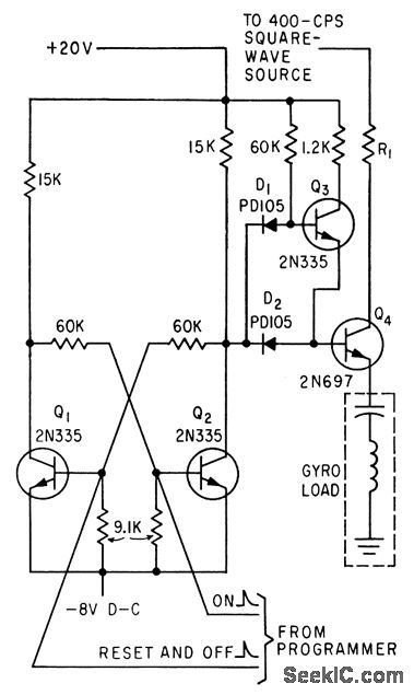
Flip-flop Q1-Q2 controls Q3 driving switching transistor Q4.Trigger signals from telemetry receiver programmer control state of flip-flop. Can pass 400-cps square wave with 10-V peak.-J. H.Porter, Miniaturized Autopilot System for Missiles, Electronics, 33:43, p60-64. (View)
View full Circuit Diagram | Comments | Reading(971)
FULL_WAVE_TD_SCR_CONTROL
Published:2009/7/13 3:51:00 Author:May
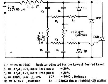
Use of funnel diode between gate and cathode of each scr improves control performance of scr, to give triggering rcmge of 10° to 175°. Input sensor Rh may be photocell or any other resistive fransducer.-TD/SCR Combos for Sale, EEE, 12;3, p62-64. (View)
View full Circuit Diagram | Comments | Reading(744)
WORD_SWITCH
Published:2009/7/16 4:02:00 Author:Jessie
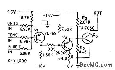
Circuit is basically bilateral switch, which closes selected word circuit of memory used in Burroughs B-215 Visible Record Computer. Units and lens inputs are used to select particular word. Third input to gate is for special-purpose inhibit instruction.-G. E. Lund and D R. Faulis, Expandable Random Access Memories, Electronics, 33:11, p 164-166. (View)
View full Circuit Diagram | Comments | Reading(659)
METAL_FORMING_CONTROL
Published:2009/7/13 3:27:00 Author:May
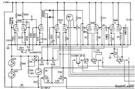
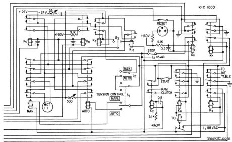
Determines yield point by sensing when tension and elongtion begin increasing at different rate during stretching and forming. Elongation signal comes from potentiometer R1, linked to ram of hydraulic relief valve. Tension signal comes from strain-gage bridge that delivers 0 to 10MV at 60 cps. At yield point.system lowers tension as dies are applied to metal. At end of cycle, operotor opens stop switch, resetting relays that are energized by power line.-G. J. Crowdes, Aulomalic Controls for Metal Working Machines.Electronics.32:10,p41-43. (View)
View full Circuit Diagram | Comments | Reading(941)
ANALOG_SIGNAL_CONTROL
Published:2009/7/13 3:26:00 Author:May
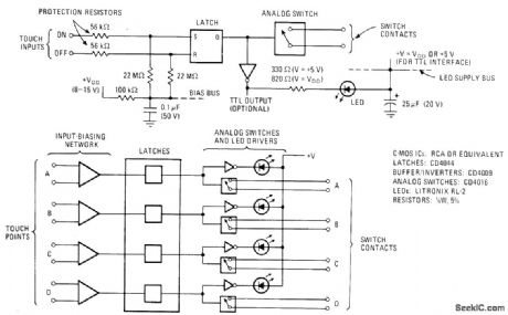
CMOS Iogic gives bounceless operation of CD4016 analog switches by sensing of ambient signals at fingertip of operator. Connections for quadruple touch-switeh arrav are shown below. Touch plates can be metal squares or disks up to 2 cm wide. If used in remote locations where power lines or other electromagnetic-field sources are not present, it may be necessary to provide grounded second contact at each sensor so slight conduction between contacts will assure triggering.-M. W. Hauser, C-MOS Touch-Switch Array Controls Analog Signals, Electronics, March 1, 1974, p 113-114; reprinted in Circuits for Electronics Engineers, Electron-ics, 1977, p 357-358. (View)
View full Circuit Diagram | Comments | Reading(1480)
LINE_DRIVER
Published:2009/7/16 3:59:00 Author:Jessie
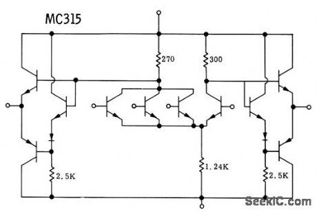
Designed as line or capacitance driver, but is same as basic gate except for output stages. Pnp transistors are hybrid, while other parts are on monolithic chip.-S. T. Robertson, Integrated Circuit Line Driver, Motorola Application Note AN-187, Aug. 1965. (View)
View full Circuit Diagram | Comments | Reading(2416)
ANALOG_TO_DIGITAL_CONVERTER_CIRCUIT
Published:2009/7/13 3:25:00 Author:May
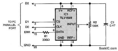
A working circuit that uses a PC parallel port to receive data from a 10-bit analog-to-digital converter (ADC) (Texas Instruments TLV1549) is shown. A fourth wire for reset can be powered from a logic-level signal. In fact, if your printer port produces 5 V (not all do), you can use the more-common TLC1549. Resistor RI reduces transmission errors by isolating the ADC from the cable capacitance; it might be unnecessary if the cable is short. (View)
View full Circuit Diagram | Comments | Reading(1172)
TV_GAME_CONTROL
Published:2009/7/13 3:15:00 Author:May
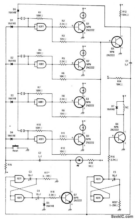
Developed for use in game in which first person to recognize musical tune places finger on touch plate to energize his lamp. Action stops cassette player andlocks out touch plates of other players. After 5-s delay, lockout is disabled so different player can have try at correct answer if first is wrong. After additional 5-s delay, relay is deenergized and music resumes. Additional reset switch is provided to reactivate all touch plates independently of delay. Supply is 12 V, and lamps are 12 V.-J. Sandler, Name That Tune, Modern Electronics, Dec. 1978, p 66 and 69-70. (View)
View full Circuit Diagram | Comments | Reading(844)
| Pages:104/312 At 20101102103104105106107108109110111112113114115116117118119120Under 20 |
Circuit Categories
power supply circuit
Amplifier Circuit
Basic Circuit
LED and Light Circuit
Sensor Circuit
Signal Processing
Electrical Equipment Circuit
Control Circuit
Remote Control Circuit
A/D-D/A Converter Circuit
Audio Circuit
Measuring and Test Circuit
Communication Circuit
Computer-Related Circuit
555 Circuit
Automotive Circuit
Repairing Circuit