
Control Circuit
Index 103
CASCADE_I_F_WITH_AGC
Published:2009/7/16 2:48:00 Author:Jessie
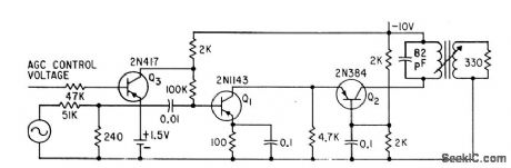
Q3 is gain control element for cascade combination Q1-Q2 in 10-Mc i-f amplifier.-J. F. Perkins, Transistor Cascade Circuit Improves Automatic Gain Control in Amplifiers, Electronics, 34:22, p 49-51. (View)
View full Circuit Diagram | Comments | Reading(1188)
PREVENTING_CLIPPING_IN_CONTROLLED_STAGE
Published:2009/7/16 2:47:00 Author:Jessie
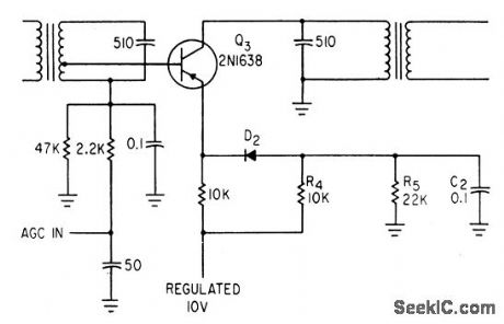
Age bias controls negative current feedback in each controlled i-f stage. Diode D2 prevents clipping when forward bias falls below peak value of signal.-P. V. Sparks, Servo Filter and Gain Control Improve Automatic Direction Finder, Electronics, 34:23, p 110-113. (View)
View full Circuit Diagram | Comments | Reading(691)
VARIABLE_GAIN_ANTENNAFIER
Published:2009/7/16 2:46:00 Author:Jessie
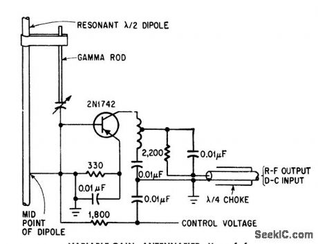
Use of forward agc permits varying gain of amplifier mounted on dipole, as required for arrays.-J. F. Rippin, Making the Antenna an Active Partner, Electronics, 38:16, p 93-96. (View)
View full Circuit Diagram | Comments | Reading(752)
AGC_FOR_WIDE_BAND_I_F
Published:2009/7/16 2:44:00 Author:Jessie
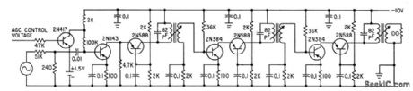
2N417 transistor is gain control element for 10-Mc tuned i-f amplifier using transistor cascade circuit. Bandwidth is 1.25 Mc and maximum gain is 91 db.-J. F. Perkins, Transistor Cascade Circuit Improves Automatic Gain Control in Amplilers, Electronics, 34:22, p 49-51. (View)
View full Circuit Diagram | Comments | Reading(902)
FET_FOR_AGC
Published:2009/7/16 2:42:00 Author:Jessie

Uses 2N2498 fet as variable-emitter resistor in common-emitter transistor amplifier. Low-current 2N3328 is used to supply constant emitter bias current and have very light dynamic loading on emitter for maximum agc range. Since variable resistor is capacitor-coupled to emitter of transistor, there is no change in bias current when strong agc voltage is suddenly applied. Absence of transient thump makes circuit desirable for broadcast speech compressors.-L. J. Sevin, Jr., Field-Effect Transistors, McGraw-Hill, N.Y., 1965, p 78. (View)
View full Circuit Diagram | Comments | Reading(2708)
PREFERRED_SQUELCH
Published:2009/7/16 2:41:00 Author:Jessie
Used in sensitive receivers having agc, to suppress objectionable increase in noise output when no signal is present, as when receiving intermittent transmissions. Uses d-c amplifier that is added to grid circuit of first audio stage to bias it beyond cutoff and there by silence it until usable signal arrives.-NBS, Handbook Preferred Circuits Navy Aeronautical Electronic Equipment, Vol.1, Electron Tube Circuits, 1963, PC 64, p 64-2. (View)
View full Circuit Diagram | Comments | Reading(904)
BRIDGE_WITH_AGC_FOR_ON_DIODE
Published:2009/7/16 2:40:00 Author:Jessie
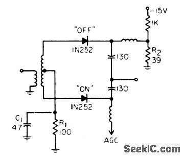
Input signal is applied in push-pull to two diodes, then combined by two capacitors. Reduction of agc bias increases attenuation of signal by bridge.-W. A Rheinfelder, Designing Automatic Gain Control Systems, EEE, 13:1, p 53-57. (View)
View full Circuit Diagram | Comments | Reading(840)
DIODE_TR_SWITCH
Published:2009/7/13 5:19:00 Author:May
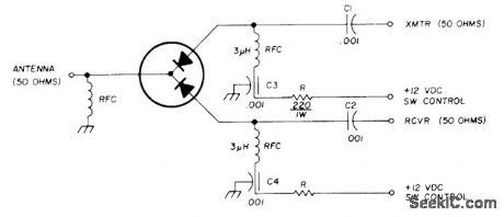
Microwave Associates MA8334 solid-state TR switch replaces conventional relays tor switching antenna back and forth between transmitter and receiver. Handles up to 50 W CW at 144 MHz, and can be used at other frequencies up to 1000 MHz by proper choice of circuit constants Measured insertion loss is 0.25 dB,and SWR is 1.23:1 when operated at 50 ohms.-T Reddeck,Solid-State VHFUHF Transmit/Receive Switch,Ham Radio,Feb1978,p 54. (View)
View full Circuit Diagram | Comments | Reading(1938)
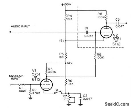
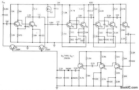
PREFERRED_AGC_AND_SQUELCH_CONTROL
Published:2009/7/16 2:39:00 Author:Jessie
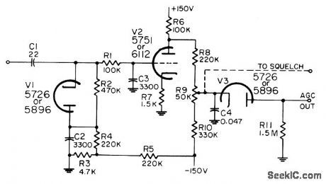
Furnishes bias voltage for r-f and i-f stages of receiver, to minimize changes in output volume as input signal fades or as receiver is tuned to station having different signal strength. Additional output controls squelch tube that suppresses background noise in absence of input signal. Maximum i-f input is 7 v rms. Maximum d-c output level is -27 v for miniature tube and -35 v for subminiature.-NBS, Handbook Preferred Circuits Navy Aeronautical Electronic Equipment, Vol. I, Electron Tube Circuits, 1963, PC 63, p 63-2. (View)
View full Circuit Diagram | Comments | Reading(870)
RISE_AND_FALL_CONTROL
Published:2009/7/16 2:39:00 Author:Jessie
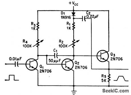
C1 controls range of rise and fall times, from 10 nsec for 10pf, to 10 millisec for 0.1 mfd. Used for testing pulse networks.-D. G. Larsen, Pulse Generator Controls Rise, Fall Time Independently, Electronics, 38:19, p 98-99.
(View)
View full Circuit Diagram | Comments | Reading(987)
TRANSISTOR_AS_ATTENUATOR
Published:2009/7/16 2:35:00 Author:Jessie
Servo-type agc for transistor receivers holds audio output constant despite changes in r-f input. Wideband low-noise amplifier is used in transmission loop, while direct-coupled grounded-emitter amplifier drives detector circuit in feedback loop.-F. Susi, Solving the AGC Di-lemma-Servo System Uses Attenuator, Electronics, 36:29, p 60-62. (View)
View full Circuit Diagram | Comments | Reading(1094)
LOG_LIMITER
Published:2009/7/13 5:00:00 Author:May
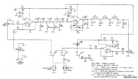
Installed between microphone and AF input connector of transmitter to increase averdge level of human voice and corresponding SSB transmitter output signal.Preamp U1 increases audio input level to over-come loss of following high-pass filter. Lowpass filter after logamp U2 eliminates all energy above about 2950 Hz. Last opamp U3 sets out.put level of processor for driving station transmitter properly. Overall amount of amplitude limiting is determined by setting of preamp gain control R4. Higffipass filter eliminates 60-Hz hum developed in audio system or in accessory equipment and reduces harmonic distortion generated by deeply pitched voice or by hum picked up from tape recorder or phone patch.Gain of opamp is determined by CR1-CR2, which give logarithmic response to audio input amplitude. Adjust R2, R17, and R19 for minimum distortion while applying 1-kHz sine wave to input.-R. Myers, A Quasi-Logarithmic Ana-Log Amplitude Limiter with Frequency-Domain Processing, QST, Aug. 1974, p 22-25 and 40. (View)
View full Circuit Diagram | Comments | Reading(1219)
HALF_WAVE_CONTROL
Published:2009/7/13 4:58:00 Author:May
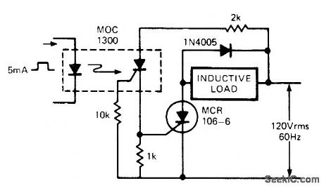
Simple AC relay operates during positive alternations of AC source, with optoisolator providing complete isolation between control circuit and SCR handling inductive load. When input LED is energized by control pulse, photo-SCR of optoisolator conducts and provides gate current for turning on power SCR. 1N4005 diode protects SCR from back EMF transients of inductive load.-T, Mazur, Solid-State Relays Offer New Solutions to Many Old Problems, EDN Magazine, Nov. 20, 1973, p 26-32. (View)
View full Circuit Diagram | Comments | Reading(1539)
SUMP_PUMP_CONTROL
Published:2009/7/13 4:56:00 Author:May
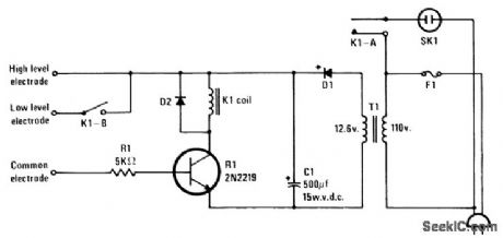
Impurities in water provide conductivity for completing circuit of transistor when water reaches level of sensing electrode, energizing relay that starts pump motor. Extra set of contacts on relay keeps motor running until water drops to predetermined lower level. Diodes are 1N4001 or equivalent, rated 1 A. Fuse should be chosen to pass normal motor current. Use 12-V double-pole relay. T1 is 300-mA filament transformer.-J. H.Gilder, Automatic Turn-On, Modern Electronics, Dec. 1978, p 78. (View)
View full Circuit Diagram | Comments | Reading(2026)
POT_CONTROL
Published:2009/7/13 4:55:00 Author:May
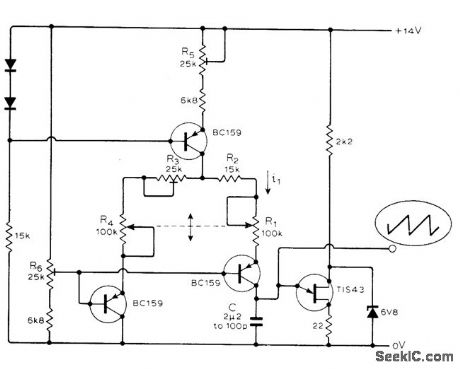
Circuit makes current through linear pot a Iinear function of rotational angle of pot. Article gives design equations. Current i1 through R1 is used to charge C, which is periodically discharged by UJT when trigger voltage is reached. Frequency of output sawtooth is proportional to i1 and hence to angle of rotation of pots. To set up, adjust pots to give maximum sawtooth frequency and ad just preset R5 for re-quired maximum frequency. Set pots to other extreme and reset R3 for required minimum frequency. -A. Armit, Linear Current/Rotation Control, Wireless World, Dec. 1975, p 576. (View)
View full Circuit Diagram | Comments | Reading(1242)
AUTOMATIC_HEADLIGHT_DIMMER
Published:2009/7/13 4:53:00 Author:May
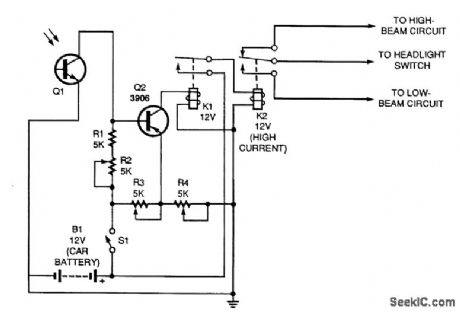
The circuit is designed to switch your car's lights from its high beams to its low beams when traffic approaches. With Q1 in moderate darkness, the variable resistors should be adjusted to produce no base current through Q2. When there are no approaching headlights to trigger the system, K1 is not energized, and its contacts remain closed. Relay K2 is energized, and the high-beam lights are on.When light from an approaching car shines on the phototransistor, the base current and collector current of the PNP transistor increase substantially, and K1 is energized. That automatically deenergizes K2 (a power-type relay fed directly by the car battery), shutting off the high-beam headlights and tuming on the low-beam lamps. Switch S1 should be conveniently located on the dash of the vehicle. Keep the switch turned off during the day so that the circuit will not leave your lights on in sunlight. (View)
View full Circuit Diagram | Comments | Reading(0)
TOUCH_SWITCH_3
Published:2009/7/13 4:51:00 Author:May
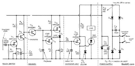
Finger on insulated metal plate applies small AC voltage (picked up by body) to FET Tr1 for amplification, to produce line-frequency square wave across R4 for application to memory section Tr3-Tr5. Charging of C3 through Tr3 and R5 produces DC output voltage across R8 that is fed to UJT Tr6 for triggering thyristor. C4 is discharged at about 10-ms intervals by Tr6 which operates from rectified AC line. For high voltage across R8, such as 4 V, thyristor is triggered early in AC cycle and maximum power is supplied to load. Diodes D4-D7 ensure that control is provided over both positive and negative half-cycles of line. The longer a finger is held on touch switch, the greater is the voltage across R8 and the more current there is through load. Removing finger turns off load, which can be lamps or other electric equipment.-R. Kreuzer, Touch-Switch Controller, Wireless World, Aug. 1971, p 389. (View)
View full Circuit Diagram | Comments | Reading(1010)
DEBOUNCING_TOUCH_SWITCH
Published:2009/7/13 4:47:00 Author:May
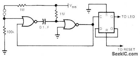
Foolproof debouncing for touch switch using toggling flip-flop (half of Motorola MC14013) is provided by two gates connected as monostable pulse stretcher. Time constant of pulse stretcher is selected to match needs of application. For status display, LED driven by 2N3903 transistor can be connected to Q terminal of flip-flop.-V. Gregory, CMOS Touch Switches-Convenient, Less $ and Sexy, EDN Magazine, May 5, 1976, p 112. (View)
View full Circuit Diagram | Comments | Reading(1621)
TOUCH_SWITCH_FOR_MUSIC_KEYBOARD
Published:2009/7/13 4:46:00 Author:May
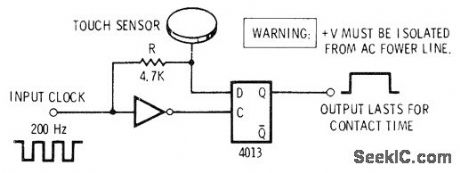
Touching metal sensor plate adds about 300pF of capacitance between plate and ground,changing RC delay network that slows down clock waveform reaehing -D input of 4013 dual D flip-flop, making flip-flop output high for duration of contact. Circuit is repeated for each key in electronic music system.-D. Lancaster, CMOS Cookbook, Howard W. Sams, Indianapolis, IN, 1977, p 278-282. (View)
View full Circuit Diagram | Comments | Reading(1053)
PROXIMITY_SWITCH_1
Published:2009/7/13 4:45:00 Author:May
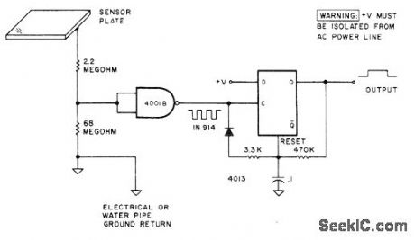
Based on coupling of human body to 60-Hz power line. Hand held close to sensor plate induces hum into 4001B gate. This is squired and used to trip 4013 retriggerable mono MVBR. Output is clean from instant of first proximity until several milliseconds after release. Sensitivity depends on size of plate.-D. Lancaster, Clocked Logic, Kilobaud, May 1977, p 24-30. (View)
View full Circuit Diagram | Comments | Reading(1051)
| Pages:103/312 At 20101102103104105106107108109110111112113114115116117118119120Under 20 |
Circuit Categories
power supply circuit
Amplifier Circuit
Basic Circuit
LED and Light Circuit
Sensor Circuit
Signal Processing
Electrical Equipment Circuit
Control Circuit
Remote Control Circuit
A/D-D/A Converter Circuit
Audio Circuit
Measuring and Test Circuit
Communication Circuit
Computer-Related Circuit
555 Circuit
Automotive Circuit
Repairing Circuit