
Circuit Diagram
Index 1302
SIMPLE_TIME_DELAY
Published:2009/6/25 21:15:00 Author:Jessie

View full Circuit Diagram | Comments | Reading(0)
ACTIVE_INDUCTOR
Published:2009/6/25 21:11:00 Author:May
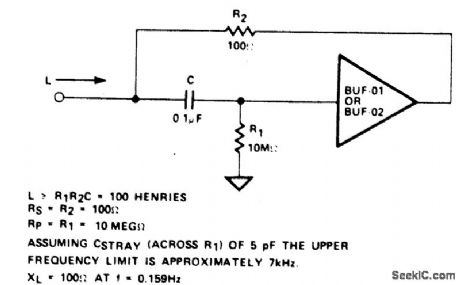
An active inductor is realized with an eight-lead IC, two carbon resistors, and a small capacitor. A commercial inductor of 50 henries may occupy up to five cubic inches. (View)
View full Circuit Diagram | Comments | Reading(2130)
AUDIO_OPERATED_RELAY
Published:2009/6/25 21:15:00 Author:Jessie
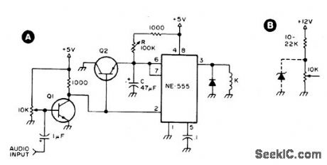
Q1 and Q2 are general purpose transis-tors. The 10 K input pot is adjusted to a point just short of where Q1 turns on as indicated by K pulling in. K is any 5 V reed relay. With the values shown for R (100 K) and C (47 μF), timing values from.05 to slightly over 5 sec-onds can be achieved. B shows the addition o f a 22 K series resistor to the 10 K input pot if a 12 V supply is used. A suitable 12 V reed relay must be used at K. (View)
View full Circuit Diagram | Comments | Reading(1932)
SIMULATED_INDUCTOR
Published:2009/6/25 21:11:00 Author:May
With a constant currentexcitation, the voltage dropped across an inductance increases with frequency. Thus, an active device whose output increases with frequency can be characterizedas an inductance. The circuit yields such a response with the effective inductance being equal to: L = R1R2C. The Q ofthis inductance depends upon RI being equal to R2.At the same time, however, the positive and negative feedback paths of the amplifier are equal leading to the distinct possibility of instability at high frequencies. R1 should, therefore, always be slightly smaller than R2 to assure stable operation. (View)
View full Circuit Diagram | Comments | Reading(0)
SOUND_EFFECT_GENERATOR
Published:2009/6/25 21:10:00 Author:May
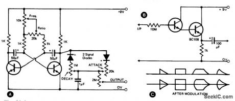
This waveshape generator is basically a slow running oscillator with variable attack and decay. A variable amplitude (high impedance) output is available via the 2 M potentiometer. B shows an add-on circuit which should be used if a low impedance output is required. Some of the output waveforms that can be produced are shown in C. (View)
View full Circuit Diagram | Comments | Reading(907)
MUSICAL_CHIME_GENERATOR
Published:2009/6/25 21:09:00 Author:May
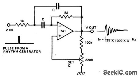
The circuit is that of a multiple feedback bandpass filter. A short click (pulse), makes it ring with a frequency which is its natural reso-nance frequency. Oscillations die away expo-nentially and closely resemble many naturally occuring percussive or plucked sounds. The higher the Q the longer the decay time constant. H igh frequencyre sonance s re semble chimes, lower frequencies sound like claves or bongos. Several circuits, all with different tuning, driven by pulses from a rhythm generator can produce an interesting pattern of sounds. (View)
View full Circuit Diagram | Comments | Reading(964)
LONG_DURATION_TIME_DELAY
Published:2009/6/25 21:14:00 Author:Jessie
View full Circuit Diagram | Comments | Reading(1)
LONG_DELAY_TIMER_USING_PUT
Published:2009/6/25 21:09:00 Author:May
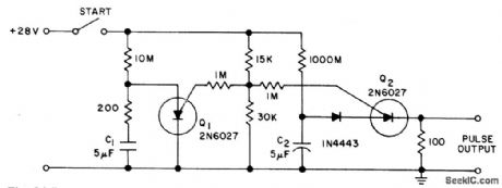
Circuit NotesThe PUT is used as both a timing element and sampling oscillator. A low leakage film capacitor is required for C2 due to the low current supplied to it. (View)
View full Circuit Diagram | Comments | Reading(663)
SHIFT_REGISTER_DRIVER
Published:2009/6/25 21:14:00 Author:Jessie
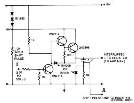
A 16 V power supply can be synthesized as shown using IN1692 rectifiers. A shift pulse input saturates the 2N2714 depriving the Darlington combination (2N2714 and 2N2868) of base drive. The negative pulse so generated on the 15 V line is differentiated to produce a positive trigger pulse at its trailing edge. (View)
View full Circuit Diagram | Comments | Reading(0)
WIDEBAND_VARIABLE_GAIN
Published:2009/6/25 21:14:00 Author:Jessie
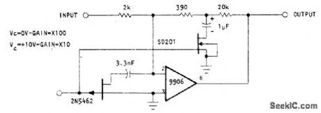
FET selves as ourPur gain-controlled device in feedback loop of Optical Electronics 9906 opamp. Resistive T network has SD201 MOS transistor as ground leg, with resistor values dlosen so transistor is electrically dose to summing junction, automatically limiting total signal voltage. Resulting arrangement of voltage-controlled feedback and compensation gives variable-gain amplifier whh good linearity and constant wideband width for all gain Ievels.- Wideband Variable Gain Amplifier, Optical Electronics, Tucson, AZ, Application Tip 10277. (View)
View full Circuit Diagram | Comments | Reading(1358)
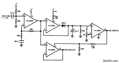
VOICE_ACTIVATED_SWITCH_AND_AMPLIFIER
Published:2009/6/25 21:14:00 Author:Jessie
View full Circuit Diagram | Comments | Reading(0)
VIDEO_AMPLIFIER
Published:2009/6/25 21:13:00 Author:Jessie
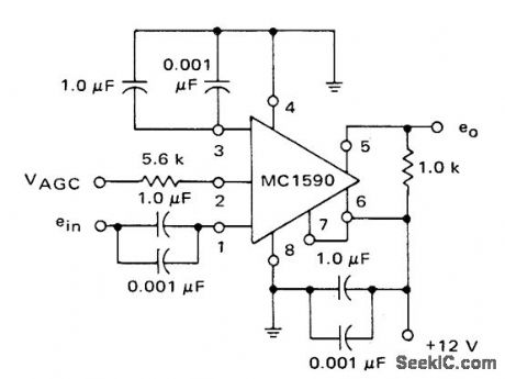
AGC capability of Motorola MC1590G makes h highly suitable for wideband video amplifier applications. Voltage gain is about 25 dB up to 50 MHz for 100-ohm load and 45 dB up to 10 MHz for 1K load. Several circuits can be cascaded to increase gain, using capacitive coupling.-B. Trout, A High Gain Inte-grated Circuit RF-IF Amplifier with Wide Range AGC, Motorola, Phoenix, AZ, 1975, AN-513, p9. (View)
View full Circuit Diagram | Comments | Reading(0)
HIGH_VOLTAGE_BUFFER
Published:2009/6/25 21:13:00 Author:Jessie
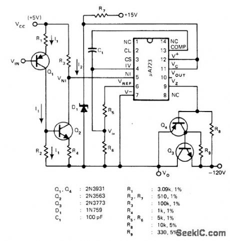


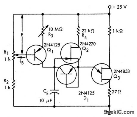
Circuit shown for μA723 voltage regulator permits use as highvoltage and high-current buffer in linear applications,Power dissipation of output transistor Q3 is only Iimiting factor,I1 is proportionalto VIN、I2 is proportional to I1, and output voltage Vo is proportional to I2 and VIN.-G. Niu, Single Op Amp Implements High-Voltage/Current Buffer, EDNMagazine, Oct 5, 1977, p 96 and 98 (View)
View full Circuit Diagram | Comments | Reading(1170)
CAPACITANCE_MULTIPLIER
Published:2009/6/25 21:09:00 Author:May
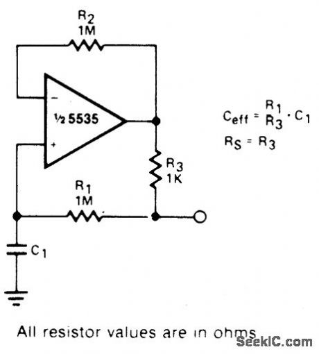
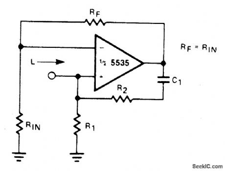
This circuit can be used to simulate large capacitances using small value components. With the values shown and C = 10 μF, an effective capacitance of 10,000 μF was obtained. The Q available is limited by the effective series resistance. So R1 should be as large as practical (View)
View full Circuit Diagram | Comments | Reading(0)
TONE_BURST_GENERATOR
Published:2009/6/25 21:09:00 Author:May
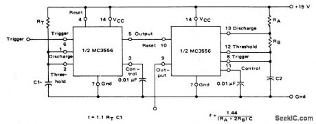
The first timer is used as a monostable and determines the tone duration when triggered by a positive pulse at pin 6. The second timer is enabled by the high output of the monostable. It is connected as an astable and determines the frequency of the tone. (View)
View full Circuit Diagram | Comments | Reading(0)
LASER_DIODE_PULSER
Published:2009/6/25 21:08:00 Author:May
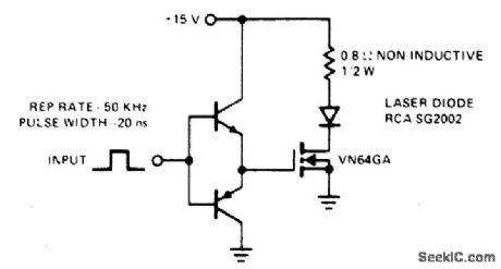
This drive is capable of driving the laser diode with 10 ampere, 20 ns pulses. For a 0.1% duty cycle, the repetition rate will be 50 kHz. A complementary emitter-follower is used as a driver. Switching speed is determined by the ft of the bipolar transistors used and the impedance of the drive source. (View)
View full Circuit Diagram | Comments | Reading(1572)
DOOR_CHIMES_DELAY
Published:2009/6/25 21:06:00 Author:May
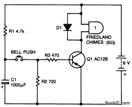
Circuit NotesWith values shown, this simple circuit will permit one operation every 10 seconds or so.Capacitor C1 charges through RI when the button is released. Making RI larger crease the delay. (View)
View full Circuit Diagram | Comments | Reading(0)
FOUR_CHANNEL_SYNTHESIZER
Published:2009/6/25 21:05:00 Author:May
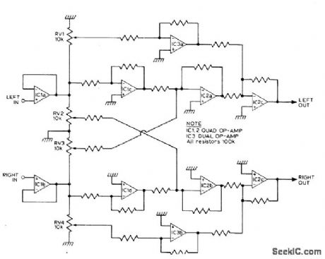
This circuit will synthesize two rear chan-nels for quadraphonic sound when fed with a stereo signal. The rear output for the left chan-nel, is a combination of the left channel input 180 out of phase, added to a proportion of the right hand channel (also out of phase). The right hand rear output is obtained in a similar way. (View)
View full Circuit Diagram | Comments | Reading(0)
MICROMETRONOME
Published:2009/6/25 21:04:00 Author:May
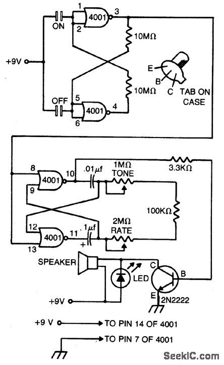
This compact metronome will run for years on a single nine-volt transistor battery.Has both tone and pulse rate controls, and uses touch plates to start and stop, can be built in a case no larger than a pack of cigarettes. The touch plates consist of two strips of metal about 1/16-inch apart mounted on, but insulated from, the case. Bridging the gap closes the switch. (View)
View full Circuit Diagram | Comments | Reading(0)
STEREO_REVERB_SYSTEM
Published:2009/6/25 21:04:00 Author:May
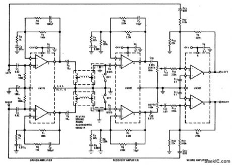
The LM378 dual power amplifier is used as the spring driver. The recovery amplifier is a low noise dual preamplifier. Mixing of the delayed signal with the original is done with another LM387 used in an inverting summing configuration. (View)
View full Circuit Diagram | Comments | Reading(0)
| Pages:1302/2234 At 2013011302130313041305130613071308130913101311131213131314131513161317131813191320Under 20 |
Circuit Categories
power supply circuit
Amplifier Circuit
Basic Circuit
LED and Light Circuit
Sensor Circuit
Signal Processing
Electrical Equipment Circuit
Control Circuit
Remote Control Circuit
A/D-D/A Converter Circuit
Audio Circuit
Measuring and Test Circuit
Communication Circuit
Computer-Related Circuit
555 Circuit
Automotive Circuit
Repairing Circuit