
Circuit Diagram
Index 1313
NEON_LAMP_DRIVER
Published:2009/6/25 2:09:00 Author:May
View full Circuit Diagram | Comments | Reading(637)
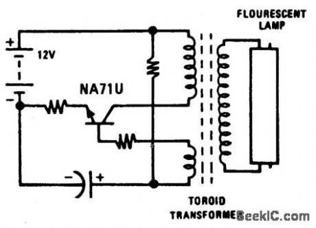
BATTERY_LANTERN_CIRCUIT_
Published:2009/6/25 2:15:00 Author:Jessie
View full Circuit Diagram | Comments | Reading(0)
EMERGENCY_LIGHT
Published:2009/6/25 2:08:00 Author:May
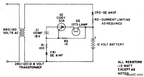
This simple circuit provides battery operated emergency lighting instantaneously upon failure of the regular ac service. When line power is restored, the emergency light turns off and the battery recharges automatically; The circuit is ideal for use in elevator cars, corridors and similar places where loss of light due to power failure would be undesirable.Completely static in operation, the circuit requires no maintenance. With ac power on, capacitor C1 charges through rectifier CR1 and resistor RI to develop a negative voltage at the gate of the C106Y SCR. By this means, the SCR is prevented from being triggered, and the emergency light stays off. At the same time, the battery is kept fully charged by rectifier CR2 and resistor R2. Should the ac power fail, C1 discharges and the SCR is triggered on by battery power through resistor R3. The SCR then energizes the emergency light. Reset is automatic when ac is restored, because the peak ac line voltage biases the SCR and turns it off. (View)
View full Circuit Diagram | Comments | Reading(9562)
RESISTANCE_TO_VOLTAGE_CONVERTER
Published:2009/6/25 2:08:00 Author:May
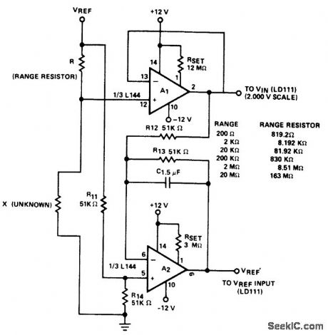
Circuit will measure accurateiy to 20 M when associated with a buffer amplifier (A1) having a low input bias current (IIN) < 30 nA). The circuit uses two of the three amplifiers contained in the Siliconix L144 micropower triple op amp. (View)
View full Circuit Diagram | Comments | Reading(1589)
HALF_WAVE_AC_PHASE_CONTROLLED_CIRCUIT
Published:2009/6/25 2:05:00 Author:May
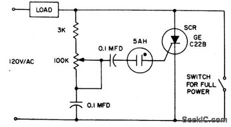
The 5AH will trigger when the voltage across the two 0.1 μF capacitors reaches the breakdown voltage of the lamp. Control can be obtained full off to 95% of the half wave RMS output voltage. Full power can be obtained with the addition of the switch across the SCR. (View)
View full Circuit Diagram | Comments | Reading(754)
COLPITTS_HARMONIC_OSCILLATOR(BASIC_CIRCUIT)
Published:2009/6/25 2:14:00 Author:Jessie
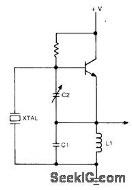
Circuit NotesThis circuit operates 30-200 ppm above series resonance. Physically simple, but analytically complex. It is inexpensive with fair frequency stability. (View)
View full Circuit Diagram | Comments | Reading(1400)
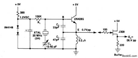
BUTLER_EMITTER_FOLLOWER_OSCILLATOR(100_MHz)
Published:2009/6/25 2:13:00 Author:Jessie
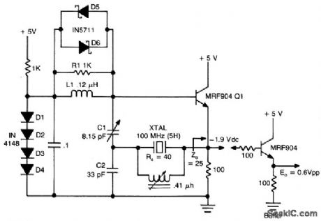
Circuit NotesThis circuit has good performance without any parasitics because emitter follower amplifier has a gain of only one with built-in negative feedback to stabilize its gain. (View)
View full Circuit Diagram | Comments | Reading(0)
TRACKING_DOUBLE_OUTPUT_BIPOLAR_SUPPLY
Published:2009/6/25 2:05:00 Author:May
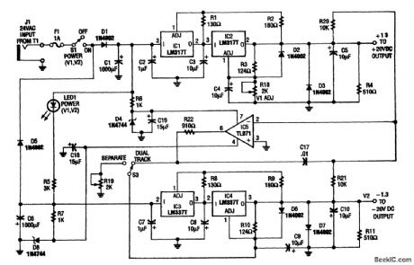
This circuit is useful for a bench supply in the lab. Separate or tracking operation is possible. The regulators should be properly heatsinked. T1 is a 24-Vac wall transformer of suitable current capacity. (View)
View full Circuit Diagram | Comments | Reading(850)
INTERNATIONAL_CRYSTAL_OF_1_LO_OSCILLATOR
Published:2009/6/25 2:04:00 Author:May
Circuit Notes
International Crystal OF-1 LO oscillator circuit for fundamental-mode crystals. (View)
View full Circuit Diagram | Comments | Reading(713)
CURRENT_TO_VOLTAGE_CONVERTER
Published:2009/6/25 2:12:00 Author:Jessie
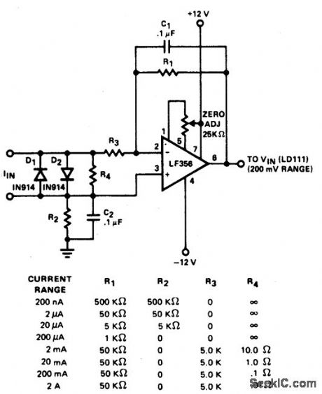
Converter features eight decades of cur-rent range. The circuit is intended to be used with the 200.0 mV range of a DVM. (View)
View full Circuit Diagram | Comments | Reading(2896)
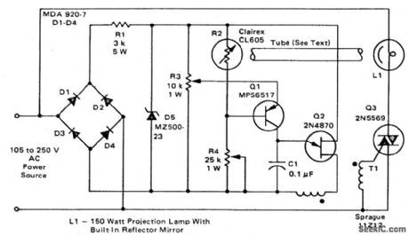
LOW_LOSS_BRIGHTNESS_CONTROL
Published:2009/6/25 2:04:00 Author:May
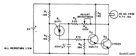
This circuit changes the average value of the dc supply voltage because of the high switching frequency. The tungsten lamp will have an almost continuous adjustable light output between 0 and 100%. If a light emitting diode is used as the emitting device, the iradiance will be in phase with the applied current pulses and will decrease to zero when the supply current is zero. (View)
View full Circuit Diagram | Comments | Reading(744)
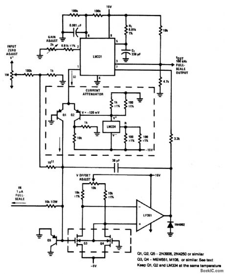
PICOAMPERE_TO_FREQUENCY_CONVERTERS
Published:2009/6/25 2:03:00 Author:May
View full Circuit Diagram | Comments | Reading(643)
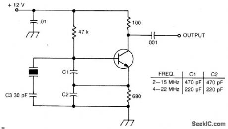
COLPITTS_HARMONIC_OSCILLATOR(100_MHz)
Published:2009/6/25 2:03:00 Author:May
Circuit Notes
L1C1 are selected to be resonant at a frequency below the desired crystal harmonic but above the crystal's next lower odd har-monic. C2 should have a value of 30-70 pF, independent of the oscillation frequency.There is no requirement for any specific ratio of C1/C2, but practical harmonic circuits seem to work best when C1 is approximately 1-3 times the value of C2. Diodes Dl-D3 provide a simple regulated bias supply. The resistance of RI should be as high as possible, as it affects the crystal's in-circuit Q. (View)
View full Circuit Diagram | Comments | Reading(948)
ZERO_POINT_SWITCH
Published:2009/6/25 2:01:00 Author:May
View full Circuit Diagram | Comments | Reading(1385)
LOW_COST_LAMP_DIMMER
Published:2009/6/25 1:59:00 Author:May
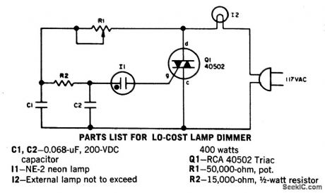
Without a heatsink, Triac Q1 handles up to a 400-watt lamp. The neon lamp does not trip the gate until it conducts so the lamp turns on a medium brilliance. The lamp can then be backed off to a soft glow. (View)
View full Circuit Diagram | Comments | Reading(2587)
800_W_SOFT_START_LIGHT_DIMMER
Published:2009/6/25 1:58:00 Author:May

View full Circuit Diagram | Comments | Reading(2415)
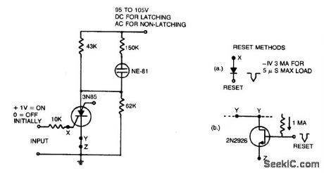
COMPLEMENTARY_AC_POWER_SWITCHING
Published:2009/6/25 2:11:00 Author:Jessie
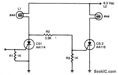
An input signal of less than 1 mA and 1 V is required to switch on CS1. As long as this input signal is maintained, CS1 will conduct during each positive half cycle of anode voltage, thereby energizing load L1 with half-wave rectified dc. L2 remains de-energized, since the anode of CS1 will not go more positive than 1.5 volts, and voltage divider R2 - R3 cannot provide enough voltage to trigger CS2. Upon removal of the input signal, CS1 will drop out.L1 will be de-energized, except for a small amount of ac current through R2 and R3. CS2will be triggered on at the beginning of each positive half-cycle, when CS1 anode voltage reaches 2 to 3 volts. CS2 will conduct for nearly the entire positive half-cycle energizing L2. It should be noted that the 6.3 volt lamps used will operate at 1/3 the rated brilliance because of the controlled switch half-wave rectifying action and will extend the operating lamp life by several orders of magnitude. Should full brilliance be desired, the anode supply voltage level should be raised to 9 volts ac. (View)
View full Circuit Diagram | Comments | Reading(1339)
LOW_COST_LAMP_DIMMER
Published:2009/6/25 1:59:00 Author:Jessie
Without a heatsink, Triac Q1 handles up to a 400-watt lamp. The neon lamp does not trip the gate until it conducts so the lamp turns on a medium brilliance. The lamp can then be backed off to a soft glow. (View)
View full Circuit Diagram | Comments | Reading(0)
800_W_SOFT_START_LIGHT_DIMMER
Published:2009/6/25 1:58:00 Author:Jessie
View full Circuit Diagram | Comments | Reading(0)
PIERCE_HARMONIC_OSCILLATOR20_MHz
Published:2009/6/25 1:57:00 Author:Jessie
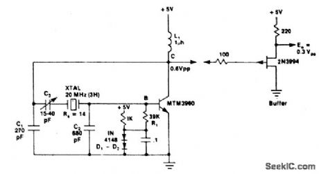
Circuit NotesThis circuit has excellent short term frequency stability because the external load tied across the crystal is mostly capacitive rather than resistive, giving the crystal a high in-circuit Q. (View)
View full Circuit Diagram | Comments | Reading(653)
| Pages:1313/2234 At 2013011302130313041305130613071308130913101311131213131314131513161317131813191320Under 20 |
Circuit Categories
power supply circuit
Amplifier Circuit
Basic Circuit
LED and Light Circuit
Sensor Circuit
Signal Processing
Electrical Equipment Circuit
Control Circuit
Remote Control Circuit
A/D-D/A Converter Circuit
Audio Circuit
Measuring and Test Circuit
Communication Circuit
Computer-Related Circuit
555 Circuit
Automotive Circuit
Repairing Circuit