
Circuit Diagram
Index 1316
REMOTE_CONTROL_FOR_LAMP_OR_APPLIANCE
Published:2009/6/25 1:38:00 Author:May
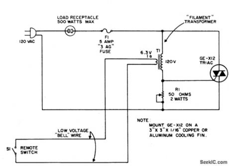
The circuit uses the primary current of a small6.3 volt filament transformer to actuate a triac and energize the load. When switch S1, in the six-volt secondary, of the transformer is open, a small magnetizing current flows through the primary winding. This magnetizing current may be large enough to trigger the triac. Therefore, a shunting resistor, R1, is required to prevent such triggering. R1, is adjusted for the highest resistance that will not cause the triac to trigger with S1 open. When single-pole remote switch, S1, closes, the secondary of the transformer is shorted and a high current flows through the 120-volt primary.This triggers the triac and energizes the load.When the triac conducts, current through the primary stops and thus prevents burning out the transformer. (View)
View full Circuit Diagram | Comments | Reading(0)
REMOTE_CONTROL_FOR_LAMP_OR_APPLIANCE
Published:2009/6/25 1:38:00 Author:Jessie
The circuit uses the primary current of a small6.3 volt filament transformer to actuate a triac and energize the load. When switch S1, in the six-volt secondary, of the transformer is open, a small magnetizing current flows through the primary winding. This magnetizing current may be large enough to trigger the triac. Therefore, a shunting resistor, R1, is required to prevent such triggering. R1, is adjusted for the highest resistance that will not cause the triac to trigger with S1 open. When single-pole remote switch, S1, closes, the secondary of the transformer is shorted and a high current flows through the 120-volt primary.This triggers the triac and energizes the load.When the triac conducts, current through the primary stops and thus prevents burning out the transformer. (View)
View full Circuit Diagram | Comments | Reading(1626)
DUAL_LIMIT_COMPARATOR
Published:2009/6/25 1:37:00 Author:May
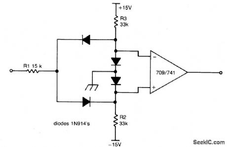
This circuit gives a positive output when the input voltage exceeds 8.5 volts. Between these limits the output is negative. The posi-tive limit point is determined by the ratio of R1, R2, and the negative point by R1, R3. The forward voltage drop across the diodes must be allowed for. The output may be inverted by reversing the inputs to the op amp. The 709 is used without frequency compensation. (View)
View full Circuit Diagram | Comments | Reading(1242)
UNDERVOLTAGE_OVERVOLTAGE_INDICATOR
Published:2009/6/25 1:36:00 Author:May
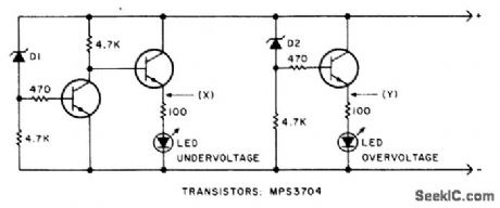
This circuit will make the LED glow if the monitored voltage goes below or above the value determined by zener diodesD1 and D2. (View)
View full Circuit Diagram | Comments | Reading(1392)
DUAL_LIMIT_COMPARATOR
Published:2009/6/25 1:37:00 Author:Jessie
This circuit gives a positive output when the input voltage exceeds 8.5 volts. Between these limits the output is negative. The posi-tive limit point is determined by the ratio of R1, R2, and the negative point by R1, R3. The forward voltage drop across the diodes must be allowed for. The output may be inverted by reversing the inputs to the op amp. The 709 is used without frequency compensation. (View)
View full Circuit Diagram | Comments | Reading(0)
LIGHT_DIMMERS
Published:2009/6/25 1:35:00 Author:May
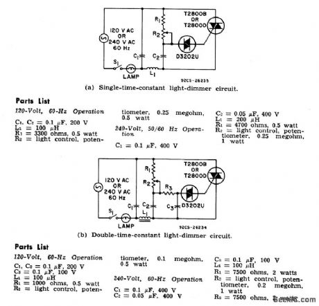
The two lamp-dimmer circuits differ in that (a) employs a s ingle-time-constant trigger network and (b) uses a double-time-constant trigger circuit that reduces hysteresis effects and thereby extends the effective range of the light-control potentiometer. (Hysteresisrefers to a difference in the control potentiometer setting at which the lamp turns on and the setting at which the light is extinguished.) The additional capacitor C2 in (b) reduces hysteresis by charging to a higher voltage than capacitor C3. During gate triggering, C3 discharges to form the gate current pulse.Capacitor C2, however, has a longer discharge time constant and this capacitor restores some of the charge removed from C3 by the gate current pulse. (View)
View full Circuit Diagram | Comments | Reading(1681)
UNDERVOLTAGE_OVERVOLTAGE_INDICATOR
Published:2009/6/25 1:36:00 Author:Jessie
This circuit will make the LED glow if the monitored voltage goes below or above the value determined by zener diodesD1 and D2. (View)
View full Circuit Diagram | Comments | Reading(0)
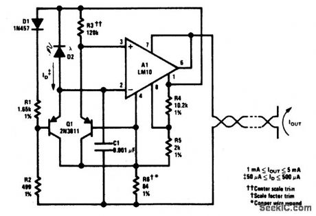
DIODE_FEEDBACK_COMPARATOR
Published:2009/6/25 1:34:00 Author:May
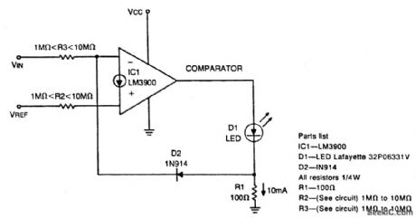
This circuit can drive an LED display with constant current independently of wide power supply voltage changes. It can operate with a power supply range of at least 4V to 30V. With 10M resistances for R2 and R3 and the inverting input of the comparator grounded, the cir-cuit becomes an LED driver with very high input impedance. The circuit can also be used in many other applications where a controllable constant current source is needed. (View)
View full Circuit Diagram | Comments | Reading(1383)
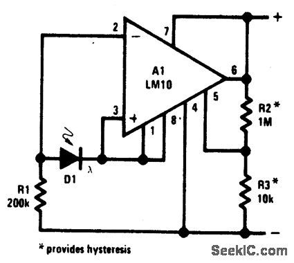
COMPARATOR_WITH_VARIABLE_HYSTERESIS_WITHOUT_SHIFTING_INITIAL_TRIP_POINT
Published:2009/6/25 1:34:00 Author:May
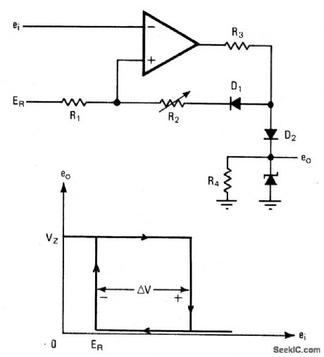
An operational amplifier can be used as a convenient device for analog comparator appli-cations that require two different trip points. The addition of a positive-feedback network introduces a precise variable hysteresis into the usual comparator switching action. Such feedback develops two comparator trip points centered about the initial trip point or refer-ence point. The voltage difference, AY, be-tween the trip points can be adjusted by varying resistor R2. When the output voltage is taken from the zener diode, as shown, it switches between zero and Vz, the zener voltage. (View)
View full Circuit Diagram | Comments | Reading(1659)
LIGHT_DIMMERS
Published:2009/6/25 1:35:00 Author:Jessie
The two lamp-dimmer circuits differ in that (a) employs a s ingle-time-constant trigger network and (b) uses a double-time-constant trigger circuit that reduces hysteresis effects and thereby extends the effective range of the light-control potentiometer. (Hysteresisrefers to a difference in the control potentiometer setting at which the lamp turns on and the setting at which the light is extinguished.) The additional capacitor C2 in (b) reduces hysteresis by charging to a higher voltage than capacitor C3. During gate triggering, C3 discharges to form the gate current pulse.Capacitor C2, however, has a longer discharge time constant and this capacitor restores some of the charge removed from C3 by the gate current pulse. (View)
View full Circuit Diagram | Comments | Reading(0)
DIODE_FEEDBACK_COMPARATOR
Published:2009/6/25 1:34:00 Author:Jessie
This circuit can drive an LED display with constant current independently of wide power supply voltage changes. It can operate with a power supply range of at least 4V to 30V. With 10M resistances for R2 and R3 and the inverting input of the comparator grounded, the cir-cuit becomes an LED driver with very high input impedance. The circuit can also be used in many other applications where a controllable constant current source is needed. (View)
View full Circuit Diagram | Comments | Reading(0)
100_kHz_CRYSTAL_CALIBRATOR
Published:2009/6/25 Author:May
Circuit Notes
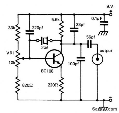
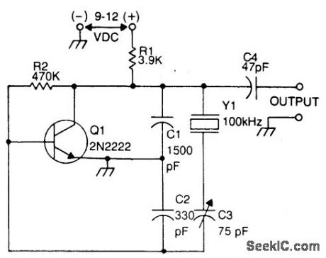
This circuit is often used by amateur radio operations, shortwave listeners, and other operators of shortwave receivers to calibrate the dial pointer. The oscillator operates at a fundamental frequency of 100 kHz, and the harmonics are used to locate points on the shortwave dial, provided that the output of the calibrator is coupled to the antenna circuit of the receiver. The crystal shunts the feedback voltage divider, and is in series with a variable capacitor (C3) that is used to set the actual operating frequency of the calibrator. (View)
View full Circuit Diagram | Comments | Reading(1)
COMPARATOR_WITH_VARIABLE_HYSTERESIS_WITHOUT_SHIFTING_INITIAL_TRIP_POINT
Published:2009/6/25 1:34:00 Author:Jessie
An operational amplifier can be used as a convenient device for analog comparator appli-cations that require two different trip points. The addition of a positive-feedback network introduces a precise variable hysteresis into the usual comparator switching action. Such feedback develops two comparator trip points centered about the initial trip point or refer-ence point. The voltage difference, AY, be-tween the trip points can be adjusted by varying resistor R2. When the output voltage is taken from the zener diode, as shown, it switches between zero and Vz, the zener voltage. (View)
View full Circuit Diagram | Comments | Reading(0)
LIGHT_LEVEL_SENSOR
Published:2009/6/24 23:53:00 Author:May
View full Circuit Diagram | Comments | Reading(1172)
FM_PRM_OPTICAL_TRANSMITTER
Published:2009/6/24 23:53:00 Author:May
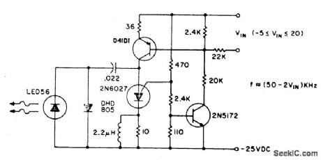
The basic circuit can be operated at 80 kHz and is limited by the PUT capacitor combi-nation. 60 kHz is the maximum modulation fre-quency. The pulse repetition rate is a linear function of VIN, the modulating voltage. Lenses or reflectors minimizes stray light noise effects. Greater output can be obtained by using a larger capacitor, which also gives a lower operating frequency, or using a higher power output IRED such as the F5D1. Average power consumption of the transmitter circuit is less than 3 watts. (View)
View full Circuit Diagram | Comments | Reading(1034)
LOGARITHMIC_LIGHT_SENSOR
Published:2009/6/24 23:51:00 Author:May
View full Circuit Diagram | Comments | Reading(1011)
HIGH_VOLTAGE_dc_GENERATOR
Published:2009/6/24 23:50:00 Author:May
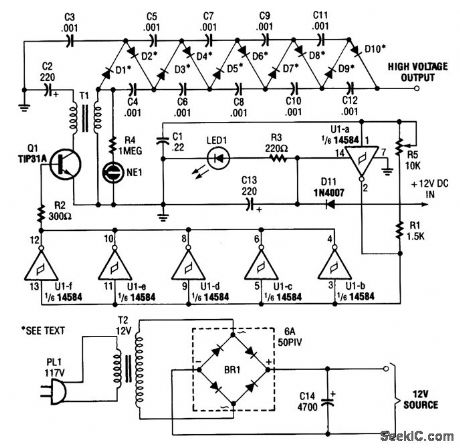
In the miniature high-voltage dc generator, the input to the circuit, taken from a 12-Vdc power supply, is magnified to provide a 10,000-Vdc output causing a pulsating signal, of opposite polarity, to be induced in T1's secondary winding.
The pulsating dc output at the secondary winding of T1 (ranging from 800 to 1000 V) is applied to a 10-stage voltage-multiplier circuit, which consists of D1 through D10, and C3 through C12. The multiplier circuit increased the voltage 10 times, producing an output of up to 10,000 Vdc. The mul-tiplier accomplishes its task by charging the capacitors (C3 through C12); the output is a series ad-dition of the voltages on all the capacitors in the multiplier.
In order for the circuit to operate efficiently, the frequency of the square wave, and therefore the signal applied to the multiplier, must be considered. The output frequency of the oscillator (U1-a) is set by the combined values of R1, R5, and C1 (which with the values specified is approximately 15 kHz). Potentiometer R5 is used to fine tune the output frequency of the oscillator. The higher the frequency of the oscillator, the lower the capacitive reactance in the multiplier.
Light-emitting diode LED1 serves as an input-power indicator, and neon lamp NE1 indicates an output at the secondary of T1. A good way to get the maximum output at the multiplier is to connect an oscilloscope to the high-voltage output of the multiplier, via a high-voltage probe, and adjust potentiometer R5 for the maximum voltage output. (View)
View full Circuit Diagram | Comments | Reading(2797)
PHOTOMULTIPLIER_SUPPLY
Published:2009/6/25 0:03:00 Author:Jessie
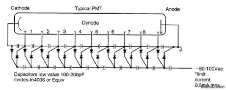
A Cockcroft-Walton voltage multiplier supplies the stepped voltage required for the dynodes of the PMT without the power-wasting voltage-divider resistor string that is traditionally used. (View)
View full Circuit Diagram | Comments | Reading(1507)
LIGHT_BEAM_OPERATED_ON_OFF_RELAY
Published:2009/6/24 23:50:00 Author:May
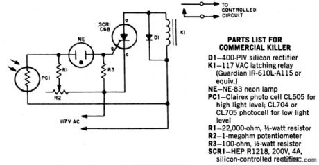
When a beam of light strikes the photocell, the voltage across neon lamp NE-1 rises sharply. NE-1 turns on and fires the SCR. K1 is an impulse relay whose contacts stay in position even after coil current is removed. The first impulse opens K1's contacts, the second impulse closes them, etc. (View)
View full Circuit Diagram | Comments | Reading(1042)
FLUORESCENT_TUBE_POWER_SUPPLY
Published:2009/6/25 0:02:00 Author:Jessie
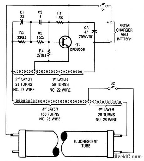
A 2N3055 oscillator (Q1) drives a homemade transformer, wound on a 5/16 × l7/8 ferrite rod. S2 is used as a filament switch and it can be eliminated, if desired. A 20-W fluorescent tube is recom-rnended. The supply is 12 V. (View)
View full Circuit Diagram | Comments | Reading(792)
| Pages:1316/2234 At 2013011302130313041305130613071308130913101311131213131314131513161317131813191320Under 20 |
Circuit Categories
power supply circuit
Amplifier Circuit
Basic Circuit
LED and Light Circuit
Sensor Circuit
Signal Processing
Electrical Equipment Circuit
Control Circuit
Remote Control Circuit
A/D-D/A Converter Circuit
Audio Circuit
Measuring and Test Circuit
Communication Circuit
Computer-Related Circuit
555 Circuit
Automotive Circuit
Repairing Circuit