
Circuit Diagram
Index 1314
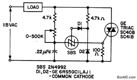
860_WATT_LIMITED_RANGE_LOW_COST_PRECISION_LIGHT_CONTROL
Published:2009/6/25 1:56:00 Author:Jessie
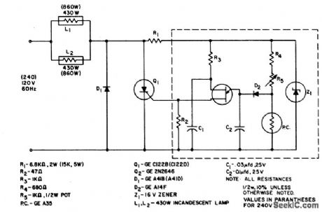
The system is designed to regulate an 860 a watt lamp load from half to full power. This is achie ved by the controlled-half-plus-fixed-half-wave phase control method. Half power applied to an incandescent lamp results in 30% of the full light output. Consequently the circuit is designed to control the light output of the lamp from 30% to 100% of maximum. (View)
View full Circuit Diagram | Comments | Reading(539)
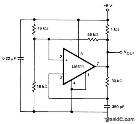
COMPARATOR
Published:2009/6/25 1:56:00 Author:Jessie
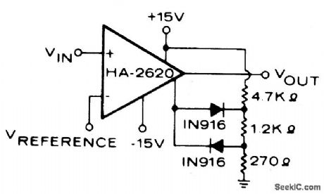
An operational amplifier is used as a comparator which is capable of driving approximately 10 logic gates. (View)
View full Circuit Diagram | Comments | Reading(0)
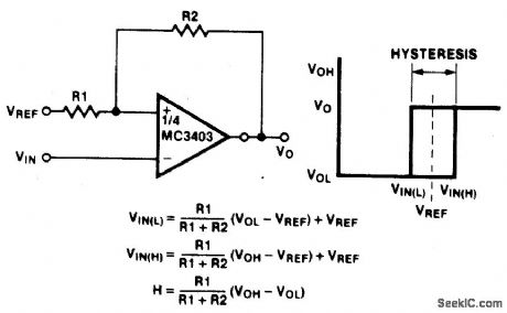
COMPARATOR_WITH_HYSTERESIS
Published:2009/6/25 1:55:00 Author:Jessie
View full Circuit Diagram | Comments | Reading(1422)
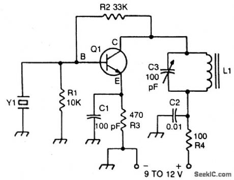
CRYSTAL_CONTROLLED_TRANSISTOR_OSCILLATOR_
Published:2009/6/25 1:54:00 Author:Jessie
View full Circuit Diagram | Comments | Reading(616)
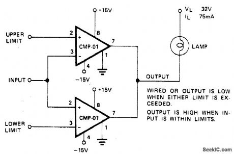
PRECISION_DUAL_LIMIT_GO_NO_GO_TESTER
Published:2009/6/25 1:53:00 Author:May
View full Circuit Diagram | Comments | Reading(0)
LIMIT_COMPARATOR_1
Published:2009/6/25 1:51:00 Author:May
View full Circuit Diagram | Comments | Reading(1008)
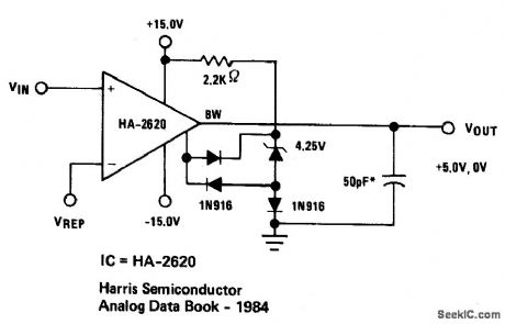
HIGH_IMPEDANCE_COMPARATOR
Published:2009/6/25 1:54:00 Author:Jessie
View full Circuit Diagram | Comments | Reading(605)
TEMPERATURE_COMPENSATED_CRYSTAL_OSCILLATOR
Published:2009/6/25 1:51:00 Author:May
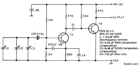
Circuit NotesTwo different negative-coefficient capacitors change in capacitance to counteract or compensate are blended to produce the desired for the decrease in frequency of the normal AT-cut characteristics. (View)
View full Circuit Diagram | Comments | Reading(0)
FULL_WAVE_SCR_CONTROL
Published:2009/6/25 1:51:00 Author:May
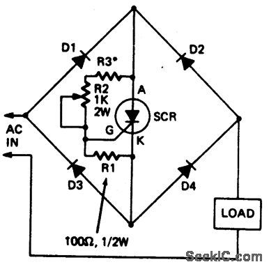
This circuit enables a single SCR to provide fullwave control of resistive loads. Resistor R3 should be chosen so that when potentiometer R2 is at its minimum setting, the current in the load is at the required minimum level. Diodes should have same current and voltage rating as the SCR. (View)
View full Circuit Diagram | Comments | Reading(975)
COLD_CATHODE_FLUORESCENT_LAMP_POWER_SUPPLY
Published:2009/6/25 1:54:00 Author:Jessie
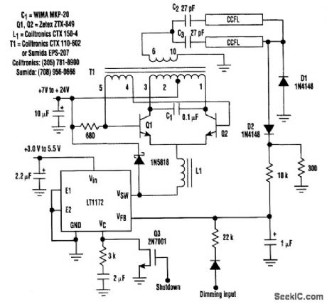
This circuit is a 92%-efficient power supply for cold-cathode fluorescent lamps (CCFLs), which are used to backlight LCD in portable equipment. The efficiency depends heavily on the component types, particularly C1, Q1, Q2, L1, and T1, whose manufacturers are noted. (View)
View full Circuit Diagram | Comments | Reading(1729)
HIGH_VOLTAGE_SUPPLY
Published:2009/6/25 1:50:00 Author:May
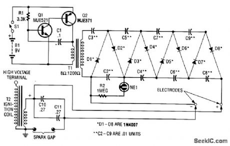
This circuit uses a transistor oscillator and a voltage multiplier to charge C10 and C11 to a high voltage. When the spark gap breaks down, T2 produces a high-voltage pulse via the capacitance discharge of C10 and C11 into its primary. T2 is an auto ignition coil. (View)
View full Circuit Diagram | Comments | Reading(3391)
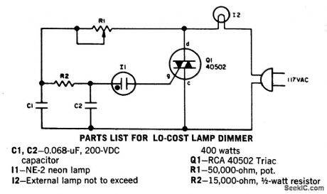
800_W_TRIAC_LIGHT_DIMMER
Published:2009/6/25 1:50:00 Author:May

View full Circuit Diagram | Comments | Reading(807)
COMPARATOR_CLOCK_CIRCUIT
Published:2009/6/25 1:50:00 Author:May
View full Circuit Diagram | Comments | Reading(655)
PRECISION_DUAL_LIMIT_GO_NO_GO_TESTER
Published:2009/6/25 1:53:00 Author:Jessie
View full Circuit Diagram | Comments | Reading(1077)
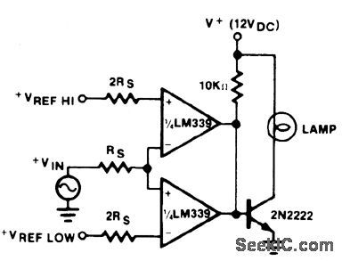
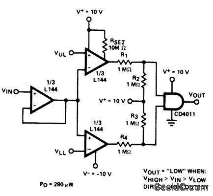
DOUBLE_ENDED_LIMIT_COMPARATOR
Published:2009/6/25 1:49:00 Author:May
View full Circuit Diagram | Comments | Reading(762)
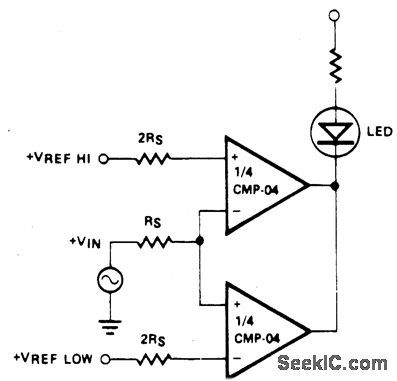
LIMIT_COMPARATOR
Published:2009/6/25 1:49:00 Author:May
View full Circuit Diagram | Comments | Reading(725)
SINGLE_CHIP_dc_SUPPLY_FOR_120_TO_240_Vac_OPERATION
Published:2009/6/25 1:48:00 Author:May
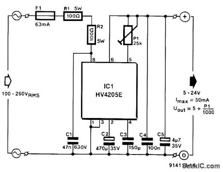
Direct derivation of 5 to 24 Vdc from ac mains, without a transformer is possible with this cir-cuit. Note that a direct mains connection to the dc output exists. Suitctble safety precautions must be taken. (View)
View full Circuit Diagram | Comments | Reading(1013)
HYSTERESIS_FREE_PHASE_CONTROL_CIRCUIT
Published:2009/6/25 1:48:00 Author:May
This circuit is intended for lamp dimming and similar applications. It requires only one RC phase lag network. To avoid the hysteresis (or snap-on ) effect, the capacitor is reset to approximately 0 volts at the end of every positive half cycle using the gate lead. (View)
View full Circuit Diagram | Comments | Reading(871)
LIMIT_COMPARATOR_1
Published:2009/6/25 1:51:00 Author:Jessie
View full Circuit Diagram | Comments | Reading(0)
TEMPERATURE_COMPENSATED_CRYSTAL_OSCILLATOR
Published:2009/6/25 1:51:00 Author:Jessie
Circuit NotesTwo different negative-coefficient capacitors change in capacitance to counteract or compensate are blended to produce the desired for the decrease in frequency of the normal AT-cut characteristics. (View)
View full Circuit Diagram | Comments | Reading(0)
| Pages:1314/2234 At 2013011302130313041305130613071308130913101311131213131314131513161317131813191320Under 20 |
Circuit Categories
power supply circuit
Amplifier Circuit
Basic Circuit
LED and Light Circuit
Sensor Circuit
Signal Processing
Electrical Equipment Circuit
Control Circuit
Remote Control Circuit
A/D-D/A Converter Circuit
Audio Circuit
Measuring and Test Circuit
Communication Circuit
Computer-Related Circuit
555 Circuit
Automotive Circuit
Repairing Circuit