
Circuit Diagram
Index 1305
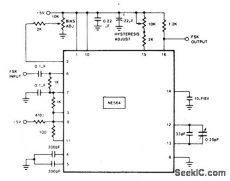
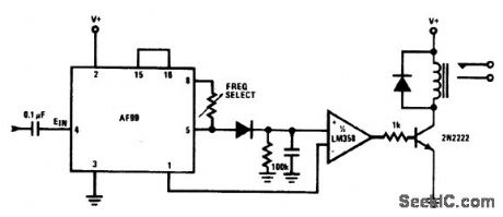
108_MHz_FSK_DECODER
Published:2009/6/25 20:54:00 Author:Jessie
View full Circuit Diagram | Comments | Reading(1014)
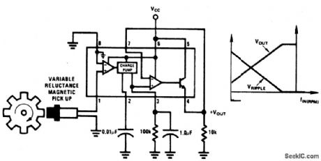
MINIMUM_COMPONENT_TACHOMETER
Published:2009/6/25 20:54:00 Author:Jessie
View full Circuit Diagram | Comments | Reading(1368)
TRANSISTOR_SORTER/TESTER
Published:2009/6/25 20:45:00 Author:May
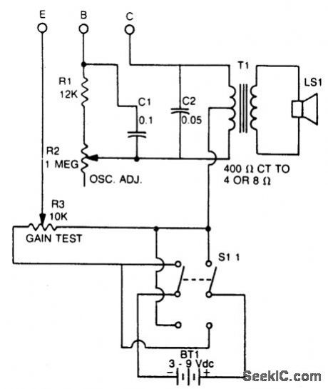
This tester checks transistor for polarity (PNP or NPN). An audible signal will give an indication of gain. Tester can also be used as a GO/NO GO tester to match unmarked devices. (View)
View full Circuit Diagram | Comments | Reading(795)
ZENER_TESTER
Published:2009/6/25 20:44:00 Author:May
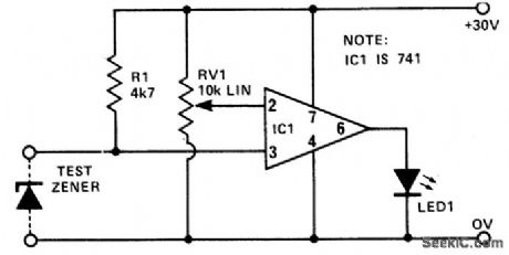
This circuit provides a low cost and reliable method of testing zener diodes. RV1 can be calibrated in volts, so that when LED 1 just lights, the voltage on pins 2 and 3 are nearly equal. Hence, the zener voltage can be readdirectly from the setting of RV1. The supply need only be as high a value as the zener itself.For a more accurate measurement, a precision pot could be added and calibrate (View)
View full Circuit Diagram | Comments | Reading(1162)
_CAPACITANCE_METER
Published:2009/6/25 20:42:00 Author:May
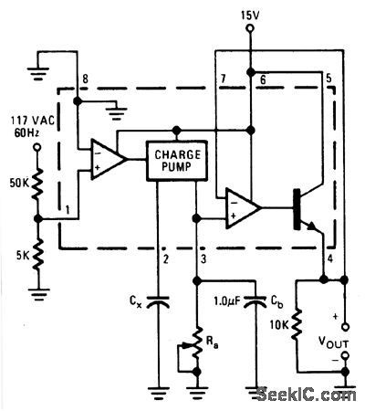
Output voltage is proportional to the capacitance connected to pin 2 of the charge pump. The meter works over a range of 0.01 to 0.1 μF with Ra set at 111 K. Over this range of capacitance, the output voltage varies from 1 to 10 volts with a 15 volt power supply. A constant frequency reference is taken from the 60-Hz line. (View)
View full Circuit Diagram | Comments | Reading(891)
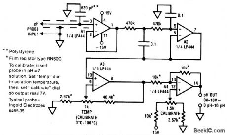
pH_PROBE_AMPLIFIER/TB_MPERATURE_COMPENSATOR
Published:2009/6/25 20:41:00 Author:May
View full Circuit Diagram | Comments | Reading(971)
SENSITIVE_RE_VOLTMETER
Published:2009/6/25 20:53:00 Author:Jessie
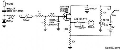
This circuit measures RF voltages beyond 200 MHz and up to about 5 V. The diode should be mounted in a remote probe, close to the probe tip. Sensitivity is excellent and voltages less than 1 V peak can be easily measured. The unit can be calibrated by connecting the input to a known level of RF voltage, such as a calibrated signal generator, and setting the calibrate control. (View)
View full Circuit Diagram | Comments | Reading(1135)
LOW_COST_pH_METER
Published:2009/6/25 20:40:00 Author:May
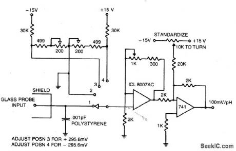
With guaranteed 1 pA input bias, the ICL 8007A is ideal as a pH meter or long term sample and hold. (View)
View full Circuit Diagram | Comments | Reading(2005)
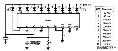
VIBRATION_METER
Published:2009/6/25 20:52:00 Author:Jessie
View full Circuit Diagram | Comments | Reading(2185)
DIGITAL_WEIGHT_SCALE
Published:2009/6/25 20:38:00 Author:May
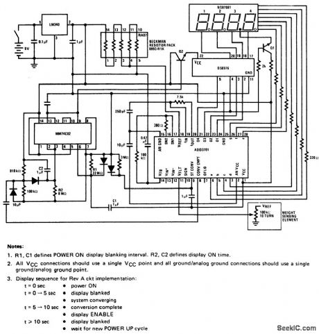
This circuit employs a potentiometer as the weight sensmg element.An object placed upon the scale displaces the potentiometer wiper,an amount proportional to its weight.Conversion of the wiper voltage to digital infomation is performed,decoded,and interfaced to the numerlc display. (View)
View full Circuit Diagram | Comments | Reading(5278)
SCA_BACKGROUND_MUSIC_DECODER
Published:2009/6/25 20:52:00 Author:Jessie
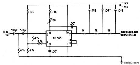
A resistive voltage divider is used to es-tablish a bias voltage for the input (pins 2 and 3). The demodulated (multiplex) FM signal is fed to the input through a two-stage high-pass filter, both to effect capacitive coupling and to attenuate the strong signal o f the regular chan-nel. A total signal amplitude, between 80 mV and 300 mV, is required at the input. Its source should have an impedance of less than 10,000 ohms. The Phase Locked Loop is tuned to 67 kHz with a 5000 ohm potentiometer; only ap-proximate tuning is required, since the loop will seek the signal. The demodulated output (pin 7) passes through a three-stage low-pass filter to provide de-emphasis and attenuate the high-frequency noise which often accompanies SCA transmission. The demodulated output signal is in the rder of 50m V and the frequency response extends to 7 kHz. (View)
View full Circuit Diagram | Comments | Reading(0)
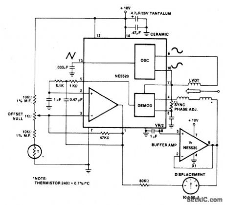
LINEAR_VARIABLE_DIFFERENTIAL_TRANSFORMER(LVDT)MEASURING_GAUGE
Published:2009/6/25 20:52:00 Author:Jessie
View full Circuit Diagram | Comments | Reading(3041)
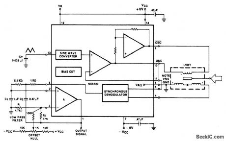
LINEAR_VARIABLE_DIFFFERENTIAL_TRANSFORMER(LVDT)DRIVER_DEMODULATOR
Published:2009/6/25 20:51:00 Author:Jessie
View full Circuit Diagram | Comments | Reading(0)
SOUND_LEVEL_MONITOR
Published:2009/6/25 20:50:00 Author:Jessie
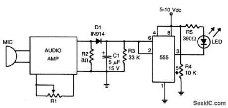
Loudness detector consists of a 555 IC wired as a Schmitt trigger. The output changes state—from high to low—whenever the input crosses a certain voltage. That threshold voltage is established by the setting of R4. (View)
View full Circuit Diagram | Comments | Reading(0)
FET_CURVE_TRACER
Published:2009/6/25 20:34:00 Author:May
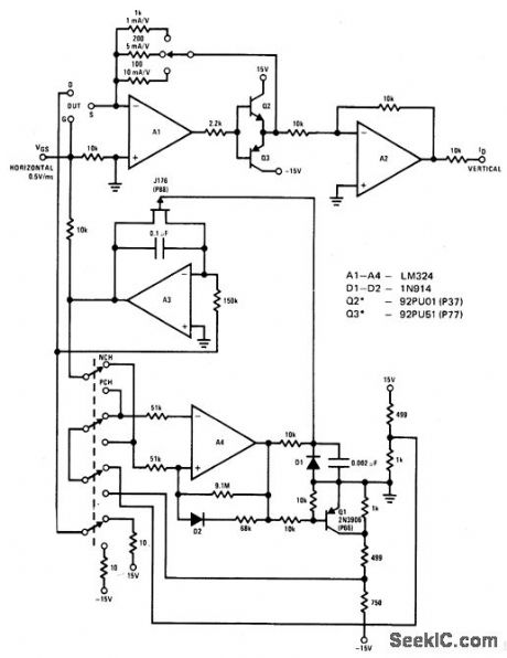
The circuit displays drain current versus gate voltage for both P and N-channel JFETS at a constant drain voltge. (View)
View full Circuit Diagram | Comments | Reading(953)
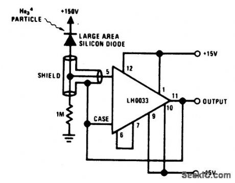
NUCLEAR_PARTICLE_DETECTOR
Published:2009/6/25 5:14:00 Author:May
View full Circuit Diagram | Comments | Reading(739)
GEIGER_COUNTER
Published:2009/6/25 5:13:00 Author:May
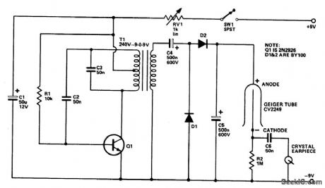
The Geiger tube needs a high voltage sup-ply which consists of Q1 and its associated components. The transformer is connected in reverse; the secondary is connected as a Hartley oscillator, and RI provides base bias.Dl, D2, C4, and C5 comprise avoltage doubler.RV1 should be set so that each click heard is nice and clean because over a certain voltage range all that will be heard is a continuous buzz. (View)
View full Circuit Diagram | Comments | Reading(0)
PEAK_LEVEL_INDICATOR
Published:2009/6/25 20:49:00 Author:Jessie
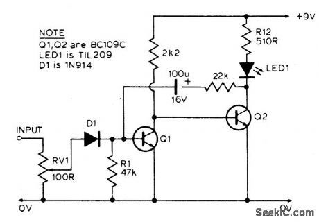
The LED is normally lit, but it will be briefly extinguished if the input exceeds a preset (by RV1) level. A possible application is to monitor the output voltage across a loudspeaker; the LED will flicker with large signals. (View)
View full Circuit Diagram | Comments | Reading(0)
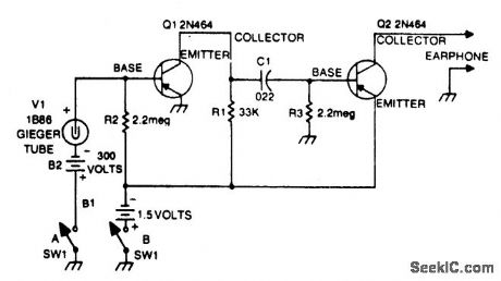
SENSITIVE_GEIGER_COUNTER
Published:2009/6/25 5:11:00 Author:May
View full Circuit Diagram | Comments | Reading(641)
TONE_DECODER_WITH_RELAY_OUTPUT
Published:2009/6/25 20:48:00 Author:Jessie
View full Circuit Diagram | Comments | Reading(1705)
| Pages:1305/2234 At 2013011302130313041305130613071308130913101311131213131314131513161317131813191320Under 20 |
Circuit Categories
power supply circuit
Amplifier Circuit
Basic Circuit
LED and Light Circuit
Sensor Circuit
Signal Processing
Electrical Equipment Circuit
Control Circuit
Remote Control Circuit
A/D-D/A Converter Circuit
Audio Circuit
Measuring and Test Circuit
Communication Circuit
Computer-Related Circuit
555 Circuit
Automotive Circuit
Repairing Circuit