
Circuit Diagram
Index 1303
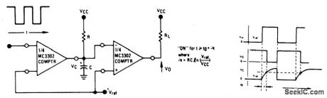
TIME_DELAY_GENERATOR
Published:2009/6/25 21:03:00 Author:May
View full Circuit Diagram | Comments | Reading(0)
SIGHT_N’SOUND_METRONOME
Published:2009/6/25 21:03:00 Author:May
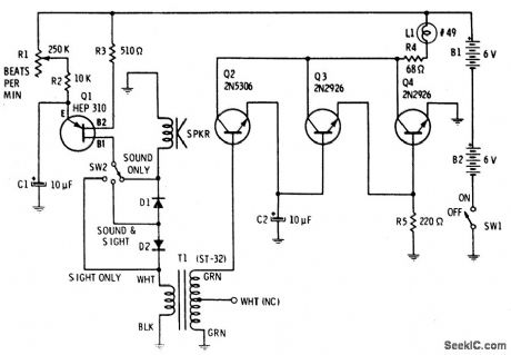
Precise, adjustable control of beats per minute from a largo of 18 to a frenzied, high presto of 500. These beiats are produced acoustically through a speaker. A light flashes at the same rate. When SW1 is closed, C1 begins to charge through R1 and R2. C1 will eventually reach a voltage at which the emitter of unijunction transistor is switched on, dumping the energy stored in C1 into an 8 ohm speaker. To produce a distinct plop , brief pulses across T2 secondary drive Q2 into conduction. The extra gain of Q3 and Q4 are sufficient to briefly switch L1 on, then off, as the pulse wave passes. Capacitor C2 stretches the pulse slightly to overcome the thermal inertia of the lamp, so that a bright flash occurs. (View)
View full Circuit Diagram | Comments | Reading(0)
LONG_TIME_DELAY
Published:2009/6/25 21:02:00 Author:May
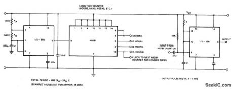
Circuit NotesIn the 556 timer, the timing is a function of the charging rate of the external capacitor. For long time delays, expensive capacitors with extremely low leakage are required. The prac-ticality of the components involved limits the time between pulses to something in the neighborhood of 10 minutes. To achieve longer time periods, both halves of a dual timer may be connected in tandem with a Divide-by ' net-work in between the first timer section oper-ates in an oscillatory mode with a period of 1/fo. This signal is then applied to a Divide-by-N network to give an output with the period of N/fo. This can then be used to trigger the second half of the 556. The total time delay is now a function of N and fo. (View)
View full Circuit Diagram | Comments | Reading(0)
ACCENTUATED_BEAT_METRONOME
Published:2009/6/25 21:01:00 Author:May
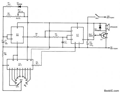
IC3 acts as an oscillator which operates if the output of IC1 is high. With the values used the two frequencies produced are about 800 Hz and 2500 Hz. The output is buffered by Q1 which drives the speaker. The first IC is used to generate the tone duration and the time interval between beats. The interval is adjustable by RV1 while the tone duration is set by R1. The output of IC1 also clocks IC2, adecade counter with 10 decoded outputs. Each of these outputs go high in sequence on each clock. The second output of IC2 is connected to the control input of IC3 and is used to change the frequency. Therefore the first tone will be high frequency, the second low and the third to tenth will be high again. This gives the 9-1 beat. If for example the 5th output is connected to the reset, the first tone will be high, the second low, and the third and fourth high, then when the 5th output goes to a high it resets it back to the first which is a high tone. We then have 3 high and one low tones or a 3-1. (View)
View full Circuit Diagram | Comments | Reading(748)
MUSICAL_ENVELOPE_GENERATOR_AND_MODULATOR
Published:2009/6/25 21:00:00 Author:May
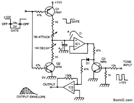
When a gate voltflge is applied, Q1 is turned on and capacitor C is charged via the attack pot in series with the 1 K resistor vary-ing this pot, attact time constant. A fast attack gives a percussive sound, a slow attack the affect of backward sounds. When the gate voltage returns to its off state, Q2 is turned on and capacitor is discharged via decay pot to ground. The envelope is buffered by IC1 and applied to Q3, which is used as a transistor chopper. A musical tone in the form of a squarewave is connected to the base of Q3.This turns the transistor on or off and thus the enve lope is chopped up at regular intervals, the intervals being determined by the pitch of the squarewave. The resultant waveform has the amplitude of the envelope and the harmonic structure of the squarewave. IC2 buffers the signal and D1 ensures that the envelope dies away at the end of a note. (View)
View full Circuit Diagram | Comments | Reading(2)
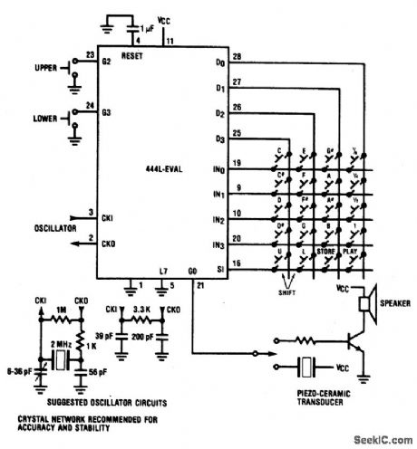
PREPROGRAMMED_SINGLE_CHIP_MICROCONTROLLER_FOR_MUSICAL_ORGAN
Published:2009/6/25 20:59:00 Author:May
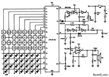
Twenty-five musical keys and 25 LEDs are provided to denote F to F with half notes in between. Memory can store a played tune. There are ten preprogrammed tunes (each has an average of 55 notes) masked in the chip. Any tune can be recalled by depressing the Tune Button followed by the corresponding Sharp Key. In team mode, the player can learn the ten preprogrammed tunes. (View)
View full Circuit Diagram | Comments | Reading(725)
LO_PARTS_TREASURE_LOCATOR
Published:2009/6/25 20:59:00 Author:May
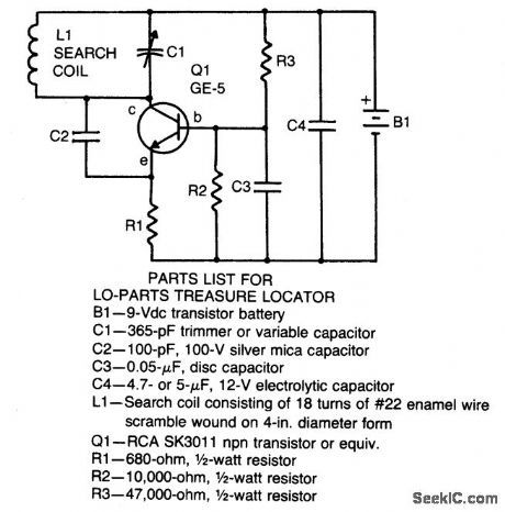
Locator uses a transistor radio as the detector. With the radio tuned to a weak station, adjust C1 so the locator oscillator beats against the received signal. When the search head pas-ses over metal, the inductance of L1 changes thereby changing the locator oscillator's frequency and changing the beat tone in the radio.The search coil consists of 18 turns of #22 enameled wire scramble wound on a 4-in.diameter form. After the coil is wound and checked for proper operation, saturate the coil with RTV adhesive for stable operation of the locator. (View)
View full Circuit Diagram | Comments | Reading(1107)
MICROPOWER_METAL_DETECTOR
Published:2009/6/25 20:57:00 Author:May
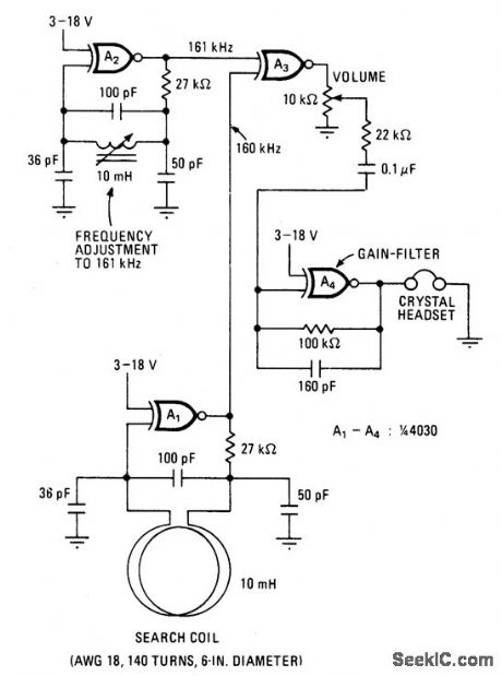
This battery-powered metal detector uses four exclusive-OR gates contained in the 4030 CMOS integrated circuit. The gates are wired as a twin-oscillators and a search coil serves as the inductance element in one of the oscillators. When the coil is brought near metal, the resultant change in its effective inductance changes the oscillator's frequency.Gates A1 and A2 form the two oscillators which are tuned to 160 and 161 kilohertz respectively. The pulses produced by each oscillator are mixed in A3, its output contains sum and difference frequencies at 1 and 321 kHz. The 321 kHz signal is filtered out by the 10 kHz low-pass filter at A4, leaving the 1 kHz signal to be amplified for the crystal headset connected at the output. The device's sensitivity is sufficient to detect coinsized objects a foot away. (View)
View full Circuit Diagram | Comments | Reading(5914)
MUSIC_SYNTHESIZER
Published:2009/6/25 20:57:00 Author:May
View full Circuit Diagram | Comments | Reading(812)
DUAL_TONE_DECODER
Published:2009/6/25 20:57:00 Author:May
View full Circuit Diagram | Comments | Reading(1)
ZENER_DIODE_CHECKER
Published:2009/6/25 20:56:00 Author:May
View full Circuit Diagram | Comments | Reading(814)
VOLTAGE_CONTROLLED_AMPLIFIER_OR_TREMOLO_CIRCUIT
Published:2009/6/25 20:56:00 Author:May
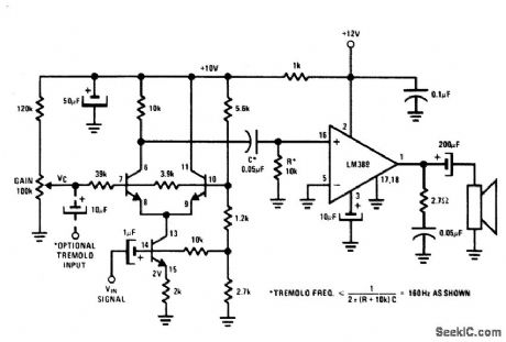
The transistors form a differential pair with an active current-source tail. This config-uration, known technically as a variable-transconductance multiplier, has an output proportional to the product of the two input signals. Multiplication occurs due to the dependence o f the transistor transconductance on the emitter current bias. Tremolo (amplitude modulation of an audio frequency by a sub-audio oscillator-normally 5-15 Hz) applica-tions require feeding the low frequency oscil-lator signal into the optional input shown. The gain control pot maybe set for optimum depth. (View)
View full Circuit Diagram | Comments | Reading(1023)
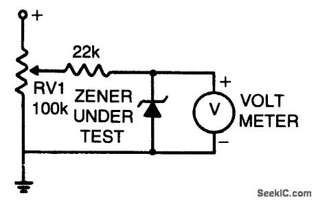
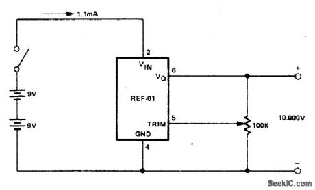
PRECISION_CALIBRATION_STANDARD
Published:2009/6/25 20:56:00 Author:May
An external power supply that gives a voltage higher than the highest expected rating of the zener diodes to be tested is required.Potentiometer RV1 is adjusted until the meter reading stabilizes. This reading is the zener diode's breakdown voltage. (View)
View full Circuit Diagram | Comments | Reading(700)
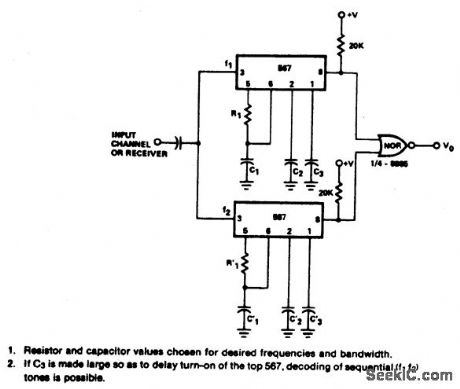
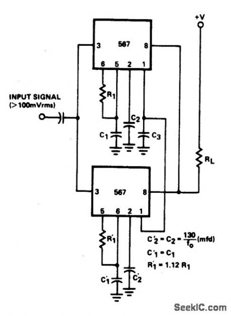
24%BANDWIDTH_TONE_DECODER
Published:2009/6/25 20:55:00 Author:May
View full Circuit Diagram | Comments | Reading(635)
PHASE_METER
Published:2009/6/25 20:55:00 Author:May

View full Circuit Diagram | Comments | Reading(0)
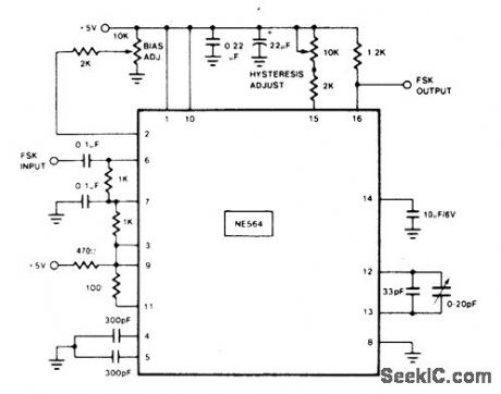
108_MHz_FSK_DECODER
Published:2009/6/25 20:54:00 Author:May
View full Circuit Diagram | Comments | Reading(0)
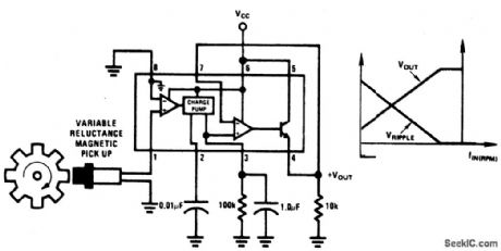
MINIMUM_COMPONENT_TACHOMETER
Published:2009/6/25 20:54:00 Author:May
View full Circuit Diagram | Comments | Reading(0)
SENSITIVE_RE_VOLTMETER
Published:2009/6/25 20:53:00 Author:May
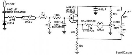
This circuit measures RF voltages beyond 200 MHz and up to about 5 V. The diode should be mounted in a remote probe, close to the probe tip. Sensitivity is excellent and voltages less than 1 V peak can be easily measured. The unit can be calibrated by connecting the input to a known level of RF voltage, such as a calibrated signal generator, and setting the calibrate control. (View)
View full Circuit Diagram | Comments | Reading(0)
LASER_DIODE_PULSER
Published:2009/6/25 21:08:00 Author:Jessie
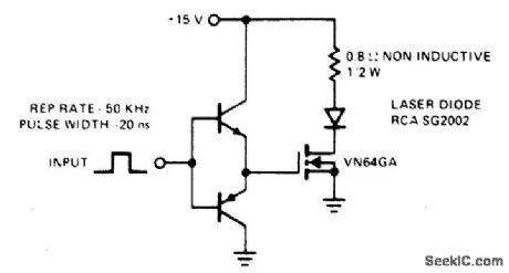
This drive is capable of driving the laser diode with 10 ampere, 20 ns pulses. For a 0.1% duty cycle, the repetition rate will be 50 kHz. A complementary emitter-follower is used as a driver. Switching speed is determined by the ft of the bipolar transistors used and the impedance of the drive source. (View)
View full Circuit Diagram | Comments | Reading(0)
INTERCOM
Published:2009/6/25 21:06:00 Author:Jessie
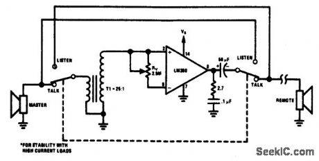
The circuit provides a minimum component intercom. With switch S1 in the talk position, the speaker of the master station acts as the microphone with the aid of stepup transformer T1. A turns ratio of 25 and a device gain of 50 allows a maximum loop gain of 1250. Rv provides a common mode volume control. Switching S1 to the listen position reverses the role of the master and remote speakers. (View)
View full Circuit Diagram | Comments | Reading(0)
| Pages:1303/2234 At 2013011302130313041305130613071308130913101311131213131314131513161317131813191320Under 20 |
Circuit Categories
power supply circuit
Amplifier Circuit
Basic Circuit
LED and Light Circuit
Sensor Circuit
Signal Processing
Electrical Equipment Circuit
Control Circuit
Remote Control Circuit
A/D-D/A Converter Circuit
Audio Circuit
Measuring and Test Circuit
Communication Circuit
Computer-Related Circuit
555 Circuit
Automotive Circuit
Repairing Circuit