
Circuit Diagram
Index 1310
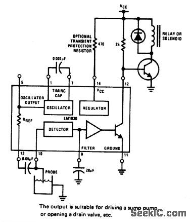
HIGH_LEVEL_WARNING_DEVICE
Published:2009/6/25 2:45:00 Author:May
View full Circuit Diagram | Comments | Reading(907)
FLUID_LEVEL_CONTROLLER
Published:2009/6/25 2:44:00 Author:May
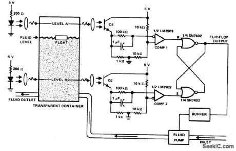
This circuit can be used to maintain fluid between two levels. Variations on this control circuit can be made to keep something that moves within certain boundary conditions. (View)
View full Circuit Diagram | Comments | Reading(691)
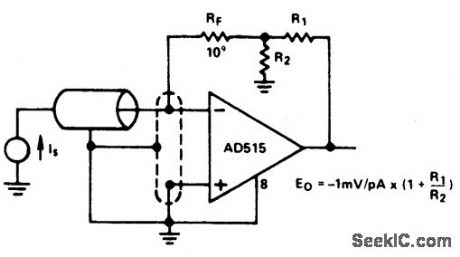
PICOAMPERE_TO_VOLTAGE_COMVERTER_WITH_GAIN
Published:2009/6/25 2:43:00 Author:May
View full Circuit Diagram | Comments | Reading(797)
LEVEL_SENSOR_FOR_CRYOGENIC_FLUIDS
Published:2009/6/25 2:43:00 Author:May
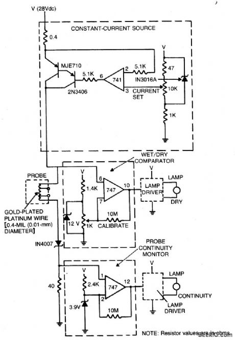
The sensor circuit is adaptable to different liquids and sensors. The constant-current source drives current through the sensing probe and a fixed resistor. The voltage-comparator circuits interpret the voltage drops to tell whether the probe is immersed in liquid and whether there is current in the probe. (View)
View full Circuit Diagram | Comments | Reading(972)
TTL_TO_MOS_LOGIC_CONVERTER
Published:2009/6/25 2:39:00 Author:May
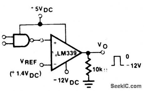
View full Circuit Diagram | Comments | Reading(0)
SINE_WAVE_TO_SQUARE_WAVE_CONVERTER
Published:2009/6/25 2:38:00 Author:May
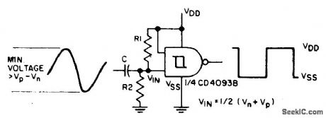
The sine input is ac coupled by capacitor C; R1 and R2 bias the input midway between Vn and Vp, the input threshold voltages, to provide a square wave at the output. (View)
View full Circuit Diagram | Comments | Reading(0)
INDUCTORLESS_SWITCHING_REGULATOR
Published:2009/6/25 2:37:00 Author:May
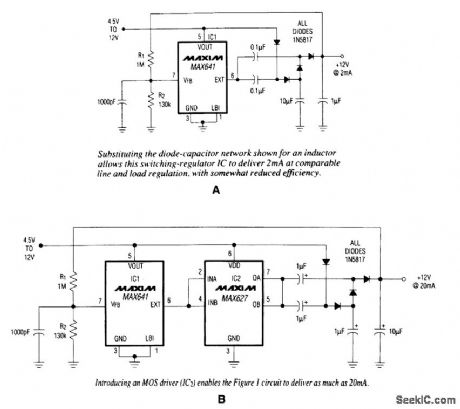
In conventional applications, switching-regulator ICs regulate 6,, by controlling the current through an external inductor. The IC in A, however, driving a diode-capacitor network in place of the inductor, offers comparable performance for small loads. The network can double, triple, or quadru-ple the input voltage.
Feedback from the R1/R2 voltage divider enables IC1 to set the regulated-output level. (As shown, the circuit derives 12 V from a 5- to 12-V input and provides as much as 2 mA of output cur-rent.) Adding a noninverting MOS driver (B) boosts the available output current to 20 mA. Substi-tuting the diode-capacitor network shown for an inductor allows this switching-regulator IC to deliver 2 mA at comparable line and load regulation, with somewhat reduced efficiency. (View)
View full Circuit Diagram | Comments | Reading(870)
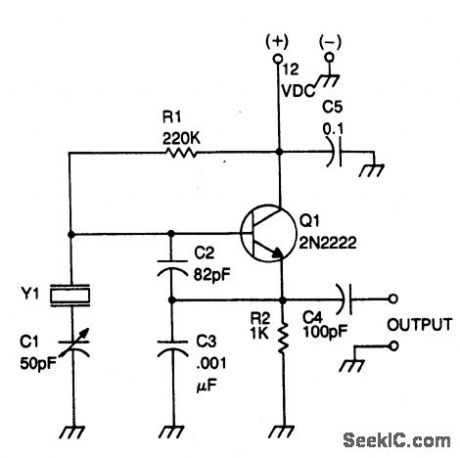
PIERCE_OSCILLATOR
Published:2009/6/25 2:36:00 Author:May
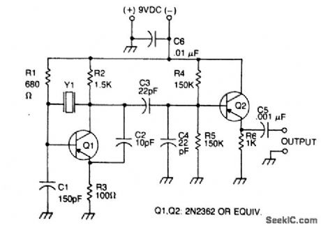
Circuit Notes
The oscillator transistor is Q1, and the crystal is placed between the collector and base. Feedback is improved by the use of the collector-emitter capacitor C2. Transistor Q2 is used as an output buffer. (View)
View full Circuit Diagram | Comments | Reading(0)
FAST_LOGARITHMIC_CONVERTER
Published:2009/6/25 2:36:00 Author:May

View full Circuit Diagram | Comments | Reading(915)
CRYSTAL_CONTROLLED_OSCILLATOR
Published:2009/6/25 2:35:00 Author:May
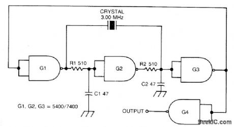
Circuit Notes
This circuit oscillates without the crystal. With the crystal in the circuit, the frequency will be that of the crystal. The circuit has good starting characteristics even with the poorest crystals. (View)
View full Circuit Diagram | Comments | Reading(0)
COLPITTS_OSCILLATOR
Published:2009/6/25 2:32:00 Author:May
Circuit Notes
This circuit will operate with fundamental-mode crystals in the range of 1MHz to 20 MHz,Feedback is controlled by capacitor voltage divider C2/C3.The rfvoltageacross the emitter resistor provides the basic feedback signal. (View)
View full Circuit Diagram | Comments | Reading(0)
MULTIPLEXER_BCE_TOTPARALLEL_BCD_CONVERTER
Published:2009/6/25 2:35:00 Author:Jessie
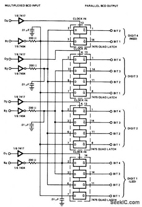
Converter consists of four quad bistable latches activated in the proper squence by the digit srtobe output of the LD110. The complemented outputs (Q) of the quad latch set reflects the state of the bit outputs when the digit strobe goes high. It will maintain this state when the digit srobe goes low. (View)
View full Circuit Diagram | Comments | Reading(920)
CRYSTAL_CONTROLLED_OSCILLATOR
Published:2009/6/25 2:35:00 Author:Jessie
Circuit Notes
This circuit oscillates without the crystal. With the crystal in the circuit, the frequency will be that of the crystal. The circuit has good starting characteristics even with the poorest crystals. (View)
View full Circuit Diagram | Comments | Reading(0)
COLPITTS_OSCILLATOR
Published:2009/6/25 2:32:00 Author:Jessie
Circuit Notes
This circuit will operate with fundamental-mode crystals in the range of 1MHz to 20 MHz,Feedback is controlled by capacitor voltage divider C2/C3.The rfvoltageacross the emitter resistor provides the basic feedback signal. (View)
View full Circuit Diagram | Comments | Reading(555)
TEMPERATURE_TO_FREQUENCY_CONVERTER
Published:2009/6/25 2:30:00 Author:Jessie
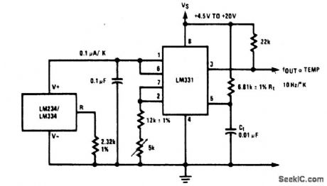
View full Circuit Diagram | Comments | Reading(0)
PRECISION_PHOTODIODE_COMPARATOR
Published:2009/6/25 2:28:00 Author:May
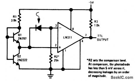
View full Circuit Diagram | Comments | Reading(1333)
3LIGHT_METER
Published:2009/6/25 2:27:00 Author:May
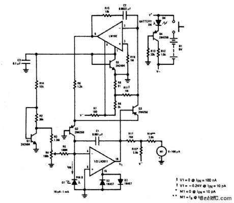
This light meter has an eight-decade range. Bias current compensation can give input current resolution of better than ±2 pA over 15 ℃ to 55℃. (View)
View full Circuit Diagram | Comments | Reading(0)
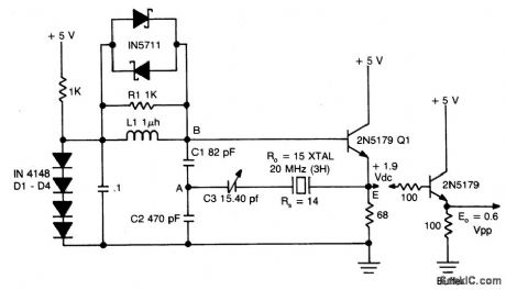
BUTLER_EMITTER_FOLLOWER_OSCILLATOR(20_MHz)
Published:2009/6/25 2:26:00 Author:May
View full Circuit Diagram | Comments | Reading(0)
WIDEBAND_HIGH_CREST_FACTOR_RMS_TO_DE_COMVERTER
Published:2009/6/25 2:26:00 Author:May
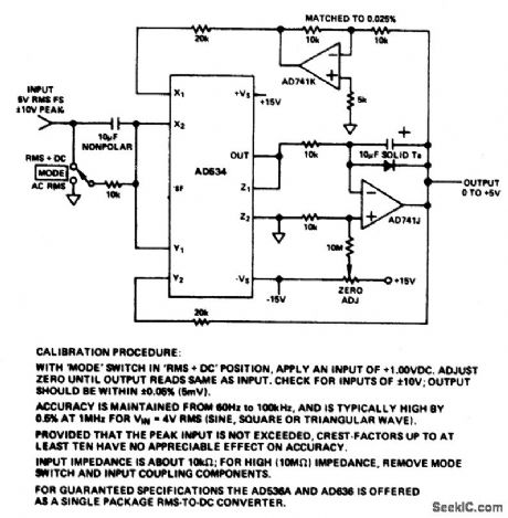
View full Circuit Diagram | Comments | Reading(0)
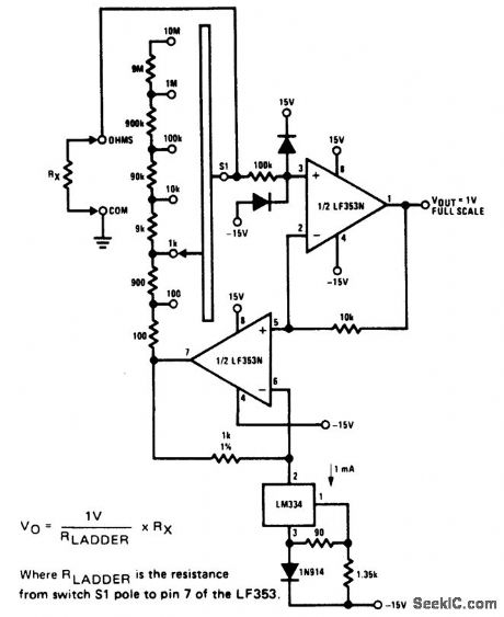
OHMS_TO_VOLTS_CONVERTER
Published:2009/6/25 2:29:00 Author:Jessie
View full Circuit Diagram | Comments | Reading(1107)
| Pages:1310/2234 At 2013011302130313041305130613071308130913101311131213131314131513161317131813191320Under 20 |
Circuit Categories
power supply circuit
Amplifier Circuit
Basic Circuit
LED and Light Circuit
Sensor Circuit
Signal Processing
Electrical Equipment Circuit
Control Circuit
Remote Control Circuit
A/D-D/A Converter Circuit
Audio Circuit
Measuring and Test Circuit
Communication Circuit
Computer-Related Circuit
555 Circuit
Automotive Circuit
Repairing Circuit