
Circuit Diagram
Index 1257
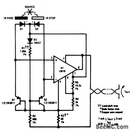
OPTICAL_PYROMETER
Published:2009/6/29 1:41:00 Author:May
View full Circuit Diagram | Comments | Reading(1025)
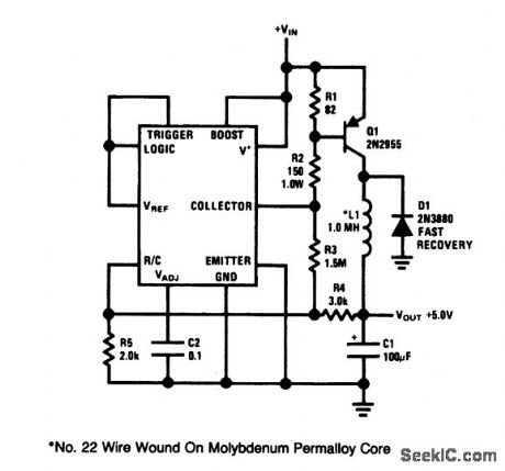
Adjustable_dc_dc_step_down_converter8_A
Published:2009/7/25 1:16:00 Author:Jessie
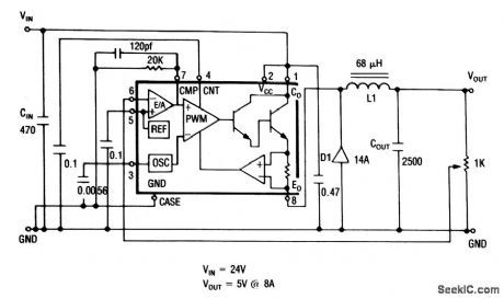
This circuit shows an LAS-6380/6480 used as a step-down converter with an adjustable output. (View)
View full Circuit Diagram | Comments | Reading(844)
Liquid measuring apparatus circuit diagram
Published:2011/8/1 3:02:00 Author:Ecco | Keyword: Liquid measuring apparatus
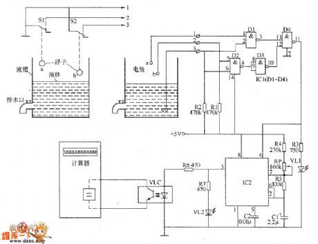
The liquid measuring apparatus circuit is composed of the liguid level control circuit, pulse generator and display circuit, and the circuit is shown as the chart. The pulse generator is composed of the time-base integrated circuit IC2, resistors R4 and R5, potentiometer RP and capacitors C1, C2. Display circuit is composed of the calculator, optocoupler VLC, LED VL2 and resistors R6, R7. R1 ~ R7 select the 1/4W metal film resistors or carbon film resistors. RP uses the organic solid potentiometer or variable resistor. C1 selects the aluminum electrolytic capacitor with the voltage in 16V.
(View)
View full Circuit Diagram | Comments | Reading(684)
Triangle_wave_to_sine_wave_converter
Published:2009/7/25 1:16:00 Author:Jessie
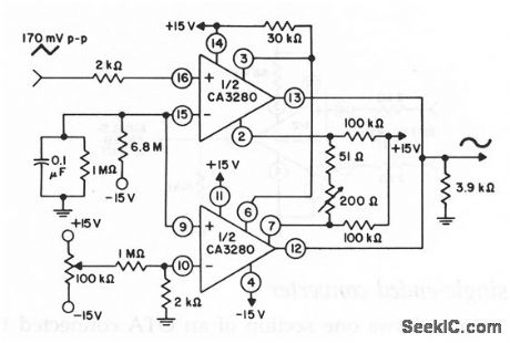
This circuit shows a triangle-wave to sine-wave converter using two sections of an OTA. Two 100-kΩ resistors are connected between the differential-amplifier emitters and U+ to reduce the current flow through the differential amplifier. This allows the amplifier to fully cut off during peak input-signal excursions. THD is about 0.37%. (View)
View full Circuit Diagram | Comments | Reading(1423)
50_kHz_BANDWIDTH
Published:2009/6/29 1:41:00 Author:May
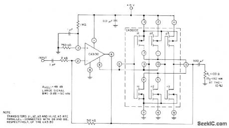
Three transistor pairs in CA3600E array are parallel-connected with output stage of CA3130 bipolar M0S opamp to boost current-handling capability about 2.5 times. Use of feedback gives closed-loop gain of 48 dB. Typical large-signal bandwidth is 50kHz for 3 dB down-″Circuit ldeas for RCA Linear ICs、″RCA Solid State Division、Somerville,NJ,1977,p 12 (View)
View full Circuit Diagram | Comments | Reading(751)
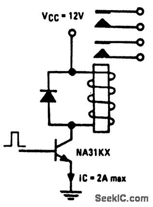
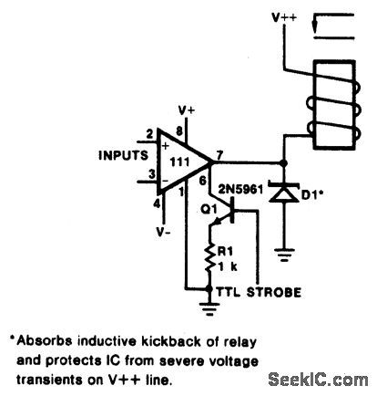
RELAY_DRIVER_
Published:2009/6/29 1:40:00 Author:May
View full Circuit Diagram | Comments | Reading(842)
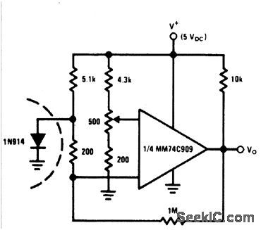
FREOUENCY_COMPARATOR
Published:2009/6/29 1:39:00 Author:May
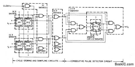
Can be used with wide range of dock frequencies up to 5.3 MHz to provide output frequency that is equal to absolute difference between input frequencies f1 and f2. Artide traces operation of circuit and gives design equations.—P. B. Morin, Frequency. Comparator Provides Difference Fre-quency, EEEMagazine, April 1971, p 65-66. (View)
View full Circuit Diagram | Comments | Reading(739)
REMOTE_TEMPERATURE_SENSING
Published:2009/6/29 1:39:00 Author:May
View full Circuit Diagram | Comments | Reading(0)
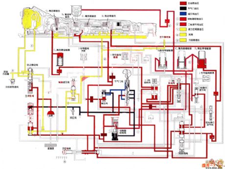
Toyota A340E S2 bit reverse oil circuit diagram
Published:2011/8/1 2:53:00 Author:Ecco | Keyword: Toyota , S2 bit, reverse oil
View full Circuit Diagram | Comments | Reading(1819)
HM4246 touching stepping dimmer circuit
Published:2011/8/1 2:51:00 Author:Ecco | Keyword: touching stepping dimmer
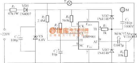
The touching stepping dimmer circuit composed of HM4246 IC is shown as the chart, when people repeatedly touch M, the light of light bulb E changes by the cycle of dark- medium- lightest- off- dark. And the corresponding crystal VTH thyristor conduction angle is 19, 75, 115 degree.
(View)
View full Circuit Diagram | Comments | Reading(908)
60_W_WITH_DC_COUPLED_OUTPUT
Published:2009/6/29 1:39:00 Author:May
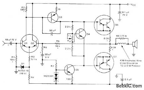
Q6 is Motorola MJE6044 complementary Darlington output transistor、and Q7 is MJE6041 Q1 and Q2 are MD8002 dual transistor,Q3 is MPS-A56, Q4 is MPS-A13 and Q5 is MPSA06.For 8-ohm loudspeaker suppiv is ±36V with 6.2K for R4、430 ohms for R5、and 33K for R7.output center oltage must be maintained at 0 VDC to ensuremaximum signal swing and prevent DC voltage from acting on loudspeaker, Frequency responseis 10 Hz to 50 kHz for -1 dB points,Samecircuit is used with different components for other powers down to 15 W and for 4-ohm loudspeaker,-R G,Ruehs,″15 to 60 Watt Audio Amplifiers Using Complementan Darlington Output Transistors,″ Motorola、 Phoenix, AZ 1974, AN-483B, p 5. (View)
View full Circuit Diagram | Comments | Reading(4102)
Electric fence control circuit 7
Published:2011/8/1 3:04:00 Author:Ecco | Keyword: Electric fence control
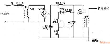
The electric fence control circuit is composed of the power supply circuit and boost circuit, and it is shown in Figure 4-32. Power supply circuit is composed of the power switch S, Fuse FU, isolation power transformer Tl, rectifier diodes VDl-VD4, filter capacitor Cl and limiting resistor Rl. Step-up circuit is composed of the resistors Rl, R2, potentiometer RP, thyristor VT, capacitor C2 and step-up transformer T2. Rl selects the 1/2W metal film resistor; R2, R3 select the 1/4W metal film resistors.
(View)
View full Circuit Diagram | Comments | Reading(5794)
Automatic charger circuit diagram
Published:2011/7/25 0:11:00 Author:Sophia | Keyword: Automatic charger
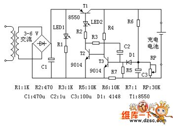
Circuit theory
The circuit is designed aiming at a single-cell Ni-MH battery. Figure: electricity is transformed through the transformer and rectified by full-bridge. Capacitor C1 is filtered into DC. LED1 is the power indicator, LED2 is the charge indicator. T1 is the charge control transistor, which works in the switch state; T2, T3 and C2 constitute a monostable flip-flop. R6 and RP constitute a limited pressure sampling circuit. R7 is limiting the sampling resistor.
Standby: the power must be on, if not, transistor T2 will be cut-off because of no base voltage, and transistor T1 is also closed, no voltage is outputed. At this moment, only the power indicator LED1 lights.
(View)
View full Circuit Diagram | Comments | Reading(1568)
Switching_regulator_using_a_timer
Published:2009/7/25 0:21:00 Author:Jessie
This circuit uses an LM122 timer to provide switching regulation. (The internal reference and comparator of the timer are used to drive a pnp switch transistor). Circuit features include a 5.5-V minimum input voltage at 1-A output current, low parts count, and good efficiency (greater than 75% ) for input voltages up to 10 V. Output ripple at the switching frequency is about 30 mV. Other values for Vout can be obtained with corresponding values of R2, R3, R4, and R5. (View)
View full Circuit Diagram | Comments | Reading(738)
Fixed_off_time_motor_control
Published:2009/7/25 0:18:00 Author:Jessie
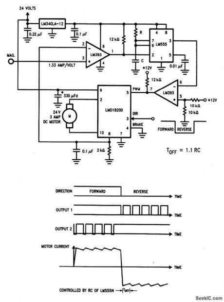
As shown by the waveforms in Fig. 3-31B, motor current modulates or dithers about a preset level, depending on the timer LM555 off-time (set by selection of R and C). The direction of motor rotation is set by the logic level at pin 3 of the LMD18200. (View)
View full Circuit Diagram | Comments | Reading(1009)
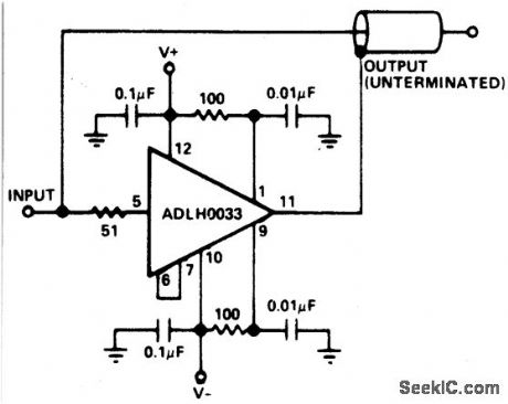
HIGH_SPEED_SHIELD_LINE_DRIVER_
Published:2009/6/29 1:39:00 Author:May

View full Circuit Diagram | Comments | Reading(675)
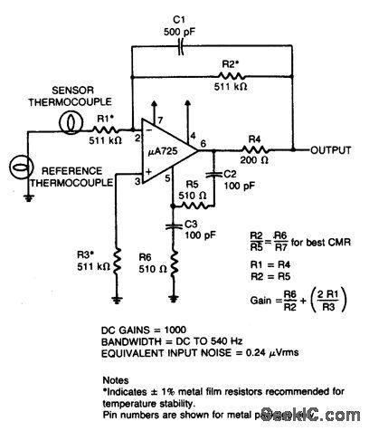
THERMOCOUPLE_AMPLIFIER
Published:2009/6/29 1:39:00 Author:May
View full Circuit Diagram | Comments | Reading(2031)
LEVEL_CROSSING_DlSPLAY
Published:2009/6/29 1:38:00 Author:May
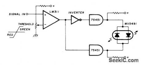
Uses Monsanto MV5491 dual red/green LED, with 220 ohms in upper lead to +5 V supply and 100 ohms in lower +5 V lead because red and green LEDs in parallel back-to-back have different voltage re quirements. Circuit requires SN75451 driver ICs and one section of SN7404 hex inverter, with LM311 comparator. All operate from single +5 V source. Provides indicator change from red to green with input change of only a few millivolts.—K. Powell, Novel Indicator Circuit, Ham Radio, April 1977, p 60-63. (View)
View full Circuit Diagram | Comments | Reading(755)
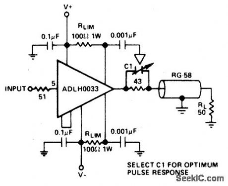
COAXIAL_CABLE_DRIVER_
Published:2009/6/29 1:38:00 Author:May
View full Circuit Diagram | Comments | Reading(757)
2_W_MONITOR
Published:2009/6/29 1:37:00 Author:May
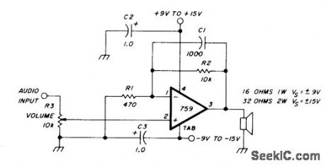
Fairdlild 759 opamp provides 1-W AF output when supply is ±9V and loudspeaker is 16 ohms,and 2 W with ±15V and 32ohm loudspeaker. Use heatsink,Gain is 20 for values shown with response rolled off at 15 kHz by C1,-W Jung,An10 Op Amp Update,Ham Radio,March 1978、p 62-69 (View)
View full Circuit Diagram | Comments | Reading(884)
| Pages:1257/2234 At 2012411242124312441245124612471248124912501251125212531254125512561257125812591260Under 20 |
Circuit Categories
power supply circuit
Amplifier Circuit
Basic Circuit
LED and Light Circuit
Sensor Circuit
Signal Processing
Electrical Equipment Circuit
Control Circuit
Remote Control Circuit
A/D-D/A Converter Circuit
Audio Circuit
Measuring and Test Circuit
Communication Circuit
Computer-Related Circuit
555 Circuit
Automotive Circuit
Repairing Circuit